Zoom lens system

Active Publication Date: 2008-08-14
ASIA OPTICAL INT LTD
View PDF5 Cites 35 Cited by
  • Summary
  • Abstract
  • Description
  • Claims
  • Application Information

AI Technical Summary

Benefits of technology

[0015]By the employment of the five lens group arrangement that has a negative-positive-negative-positive-positive refractive power configuration and that consists of only six constituent lens elements, the zoom lens system of the present invention provides the advantages of s

Problems solved by technology

However, the employment of four lens groups leads to increase in the number of constituent lens elements and thus increase in manufacturing costs.
Therefore, how to provide

Method used


Image

  • Zoom lens system
  • Zoom lens system
  • Zoom lens system

Examples


numerical embodiment 1

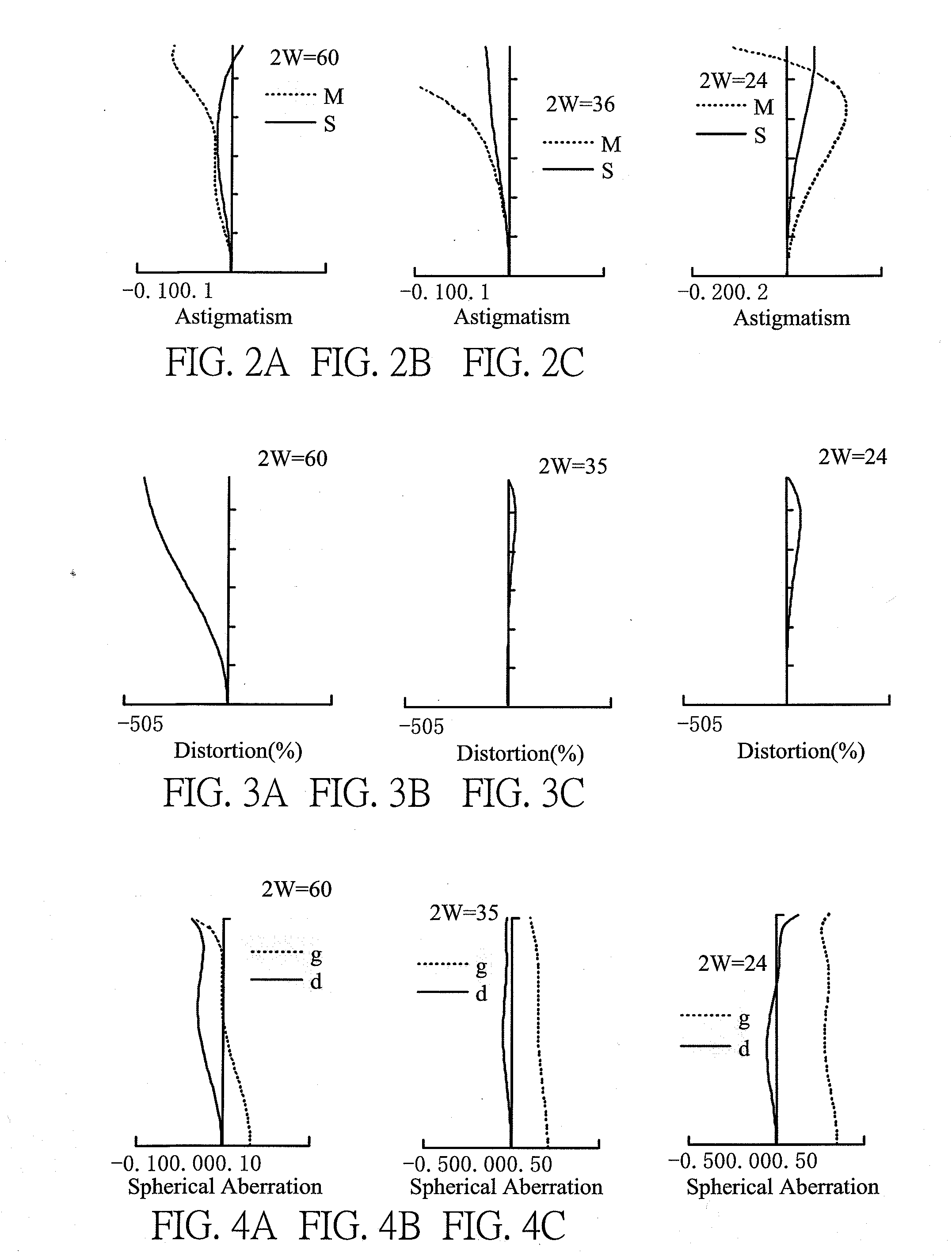
[0053]FIGS. 2A-6C illustrate various aberrations generated by the present zoom lens system according to Numerical Embodiment 1, wherein FIGS. 2A-2C are respective graphic representations of astigmatism aberration at the wide-angle end, the intermediate position and the telephoto end, FIGS. 3A-3C are respective graphic representations of distortion aberration in the different three zooming positions, FIGS. 4A-4C are respective graphic representations of spherical aberration in the different three zooming positions, FIGS. 5A-5C are respective graphic representations of chromatic aberration in the different three zooming positions, and FIGS. 6A-6C are respective graphic representations of coma aberration in the different three zooming positions.

[0054]In these graphs, “2w” denotes a view angle. In FIGS. 2A-2C, “M” denotes a meridional plane and “S” denotes a sagittal plane. In FIGS. 4A-4C, “g” denotes a spectral g-line and “d” denotes a spectral d-line.

[0055]Numerical values of the comp...

numerical embodiment 2

[0058]FIGS. 7A-11C illustrate various aberrations generated by the present zoom lens system according to Numerical Embodiment 2, wherein FIGS. 7A-7C are respective graphic representations of astigmatism aberration at the wide-angle end, the intermediate position and the telephoto end, FIGS. 8A-8C are respective graphic representations of distortion aberration in the different three zooming positions, FIGS. 9A-9C are respective graphic representations of spherical aberration in the different three zooming positions, FIGS. 10A-10C are respective graphic representations of chromatic aberration in the different three zooming positions, and FIGS. 11A-11C are respective graphic representations of coma aberration in the different three zooming positions.

[0059]Numerical values of the component lenses of the present zoom lens system according to Numerical Embodiment 2 are shown in Data Table 4 given below:

DATA TABLE 4Surface (i)Ri (mm)D (mm)NdVdR1−140.0540.71.5798463.01R25.452477D1aperture∞0...

numerical embodiment 3

[0062]FIGS. 12A-6C illustrate various aberrations generated by the present zoom lens system according to Numerical Embodiment 3, wherein FIGS. 12A-12C are respective graphic representations of astigmatism aberration at the wide-angle end, the intermediate position and the telephoto end, FIGS. 13A-13C are respective graphic representations of distortion aberration in the different three zooming positions, FIGS. 14A-14C are respective graphic representations of spherical aberration in the different three zooming positions, FIGS. 15A-15C are respective graphic representations of chromatic aberration in the different three zooming positions, and FIGS. 16A-16C are respective graphic representations of coma aberration in the different three zooming positions.

[0063]Numerical values of the component lenses of the present zoom lens system according to Numerical Embodiment 3 are shown in Data Table 7 given below.

DATA TABLE 7Surface (i)Ri (mm)D (mm)NdVdR142.557780.71.63960963.01R26.2169740.7ap...


PUM


Abstract

A zoom lens system includes, in order from an object side to an image side, first to fifth lens groups respectively having negative, positive, negative, positive, and positive refractive power. During zooming from a wide-angle end to a telephoto end, the second and third lens groups are moved independently toward the object side with spacing therebetween increased and that between the first and second lens groups decreased. The following condition is satisfied 1.05≦(fW·LW)/(fT·Y)≦1.53, wherein fW and fT are focal lengths of the zoom lens system at the wide-angle end and the telephoto end, Y represents a maximum diagonal length of an image plane, and LW represents a total length of the zoom lens system at the wide-angle end which is defined as a distance from the vertex of a first surface of the first lens on the object side to the image plane.

Description

BACKGROUND OF THE INVENTION[0001]1. Field of the Invention[0002]The present invention relates to a zoom lens system, and particularly to a small-size and low-cost zoom lens system for forming a real image on a digital or non-digital image pickup device of a camera.[0003]2. Description of Prior Art[0004]In recent years, most electronic devices, such as mobile phones, personal digital assistants (PDAs) and notebook computers, have been integrated with a photographic lens module for effecting the photographic function. Such a photographic lens module is generally required to be small in size and light in weight for portability, while providing a high level of image resolution. To satisfy these requirements, a conventional photographic lens module generally consists of three lens groups.[0005]With the development of semiconductor technology, aspheric lens elements have been widely used in a photographic lens module. Conventionally, a photographic zoom lens system generally employs three...

Claims


Application Information

Patent Timeline
IPC IPC(8): G02B15/14
CPCG02B15/177G02B13/18G02B15/145527
Inventor CHANG, YU-MIN
Owner ASIA OPTICAL INT LTD
Why Eureka
Try Eureka