Hook Ring Segment For A Compressor Vane

a compressor vane and hook ring technology, which is applied in the direction of machines/engines, liquid fuel engines, forging/pressing/hammering apparatus, etc., can solve the problems of limited damping, significant wear at the compressor vane attachment hooks and the circumferential area, and the arrangement is not ideal for engine operation. , to achieve the effect of improving the contact area between the hook ring and the compressor cas

Active Publication Date: 2008-08-14
ANSALDO ENERGIA SWITZERLAND AG
View PDF9 Cites 14 Cited by
  • Summary
  • Abstract
  • Description
  • Claims
  • Application Information

AI Technical Summary

Benefits of technology

[0010]The present invention provides embodiments for a compressor stator vane assembly in a gas turbine engine that addresses the limited damping capability of the prior art vane configuration. In an embodiment of the present invention a stator vane assembly is provided having a plurality of vanes, each vane having an attachment and channels machined into forward and aft walls of the attachment. A forward hook ring segment is pressfit into the channel in the forward wall of the attachment and an aft hook ring segment is pressfit into the channel in the aft wall of the attachment. The hook ring segments in turn engage the grooves in the compressor case, such that the contact area between the hook rings and the compressor case are significantly improved.

Problems solved by technology

However, this arrangement is not ideal for engine operation due to the mismatch between the hooks and slots and the high localized stress that occurs due to this mismatch.
Any damping that does occur for this design is limited due to the stators being individual (low mass / low inertia) and having limited contact area with the slots for reacting displacement forces.
As a result of the increased stress and limited damping, significant wear is exhibited at the compressor vane attachment hooks as well in the circumferential slot of the case.
This wear requires premature replacement of the vanes and repair to the case.

Method used


Image

  • Hook Ring Segment For A Compressor Vane
  • Hook Ring Segment For A Compressor Vane
  • Hook Ring Segment For A Compressor Vane

Examples


Embodiment Construction

[0022]The subject matter of the present invention is described with specificity herein to meet statutory requirements. However, the description itself is not intended to limit the scope of this patent. Rather, the inventors have contemplated that the claimed subject matter might also be embodied in other ways, to include different steps or combinations of steps similar to the ones described in this document, in conjunction with other present or future technologies. Moreover, although the terms “step” and / or “block” may be used herein to connote different elements of methods employed, the terms should not be interpreted as implying any particular order among or between various steps herein disclosed unless and except when the order of individual steps is explicitly described.

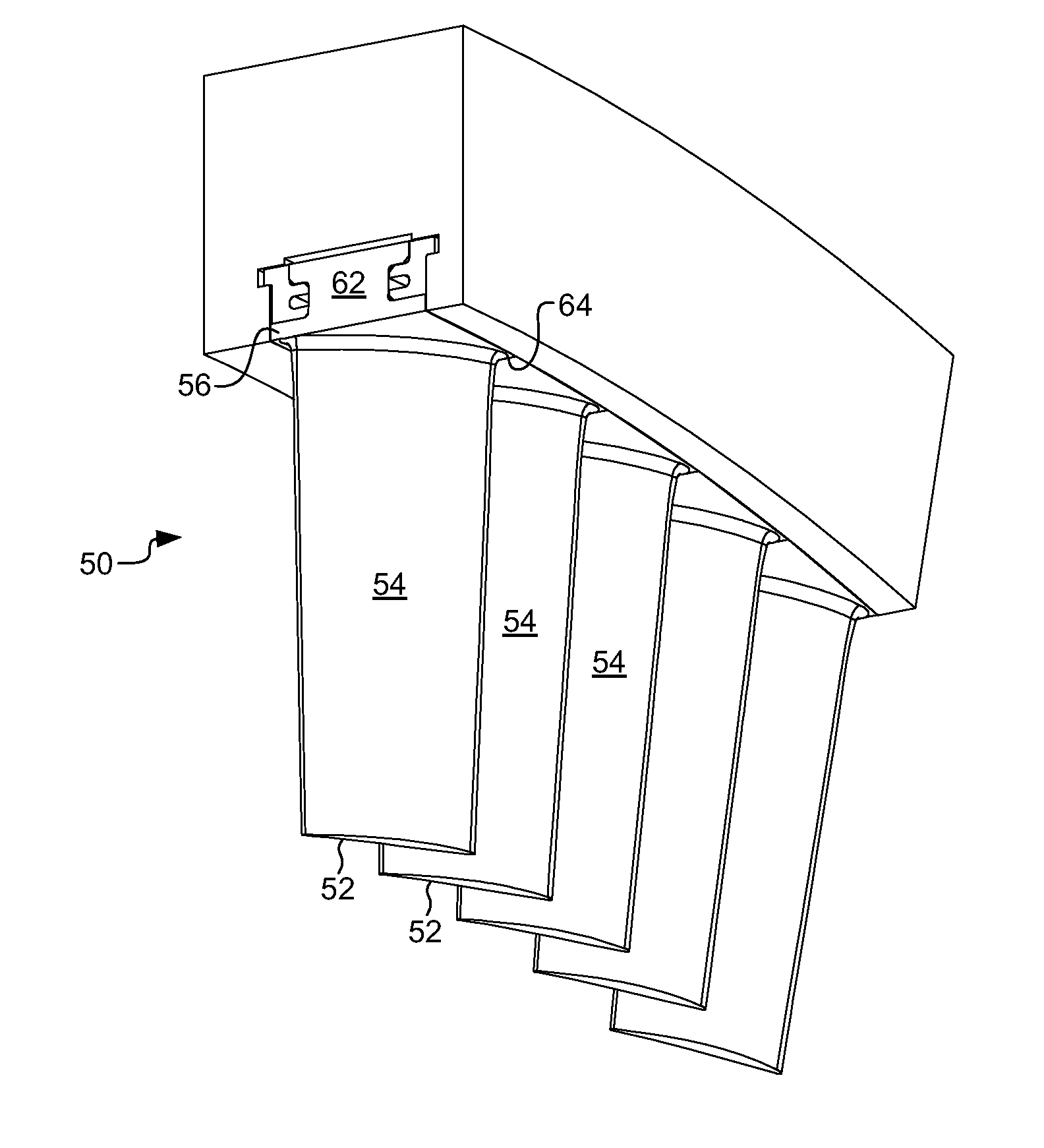
[0023]Referring now to FIGS. 4-7, the present invention provides a vane assembly 50 for reducing operating stresses and vibrations in individual vanes. The vane assembly of the present invention comprises a plura...


PUM

PropertyMeasurementUnit
angleaaaaaaaaaa
distanceaaaaaaaaaa
circumferential lengthaaaaaaaaaa

Abstract

Embodiments for a compressor stator vane assembly in a gas turbine engine are disclosed. In an embodiment of the present invention a stator vane assembly is provided having a plurality of vanes each with an attachment and channels machined into the forward and aft walls of the attachment. A forward hook ring segment is pressfit into the channel in the forward wall of the attachment and an aft hook ring is pressfit into the channel in the aft wall of the attachment. The hook ring segments join a plurality of vanes together so as to provide a uniform engagement of mounting slots in the compressor case. Such an arrangement increases the contact area between the hook rings and the compressor case such that damping of individual vane vibrations are improved and operating stresses are reduced.

Description

CROSS-REFERENCE TO RELATED APPLICATIONS[0001]Not Applicable.STATEMENT REGARDING FEDERALLY SPONSORED RESEARCH OR DEVELOPMENT[0002]Not Applicable.TECHNICAL FIELD[0003]The present invention relates to gas turbine engines. More particularly, embodiments of the present invention relate to a stator vane assembly for use in a compressor of a gas turbine engine.BACKGROUND OF THE INVENTION[0004]Gas turbine engines are typically utilized to provide thrust to an aerial vehicle or mechanical power to drive an electrical generator. Gas turbine engines comprise at least a compressor, a combustion system, and a turbine, with the turbine coupled to the compressor through a shaft.[0005]A typical compressor comprises a plurality of axially spaced and alternating rows of rotating and stationary airfoils. The rotating airfoils in the compressor are commonly referred to as blades and stationary airfoils are referred to as vanes or stators. Each stage of the blades and vanes decrease in radial height thr...

Claims


Application Information

Patent Timeline
Patent Type & Authority Applications(United States)
IPC IPC(8): F01D9/00F01D9/04F01D25/28
CPCF01D9/04F01D9/042Y10T29/49323F01D25/28F01D25/246
Inventor BRACKETT, JAMES G.ELLIS, CHARLESMCGHEE, MICHAEL DAVISSTROHL, J. PAGE
Owner ANSALDO ENERGIA SWITZERLAND AG
Why Eureka
Try Eureka