Eureka AIR delivers breakthrough ideas for toughest innovation challenges, trusted by R&D personnel around the world.

Annular Corrugated Coaxial Cable Connector with Polymeric Spring Finger Nut

a technology of polymeric spring finger nut and coaxial cable, which is applied in the manufacture of insulating conductor/cable, cable/conductor, cable/device connection, etc., can solve the problems of incompatibility of annular corrugated coaxial cable with annular corrugated solid outer conductor coaxial cable, high manufacturing cost and time-consuming installation

Inactive Publication Date: 2008-08-14
ANDREW LLC
View PDF18 Cites 32 Cited by
  • Summary
  • Abstract
  • Description
  • Claims
  • Application Information

AI Technical Summary

Benefits of technology

[0017]The inventor has recognized that a spring finger nut element of a connector according to the invention may be formed from a polymeric material via injection molding to eliminate the numerous required metal machining steps and significantly reduce materials costs and component weight. Although the connector body of a connector according to the invention may also be formed partially or completely from polymeric material, for example via overmolding or application of an internal conductive coating or separate internal conductive element, where only the metal spring finger nut is formed from polymeric material, the requirement for and associated complexities of an additional internal outer conductor conductive structure is eliminated.
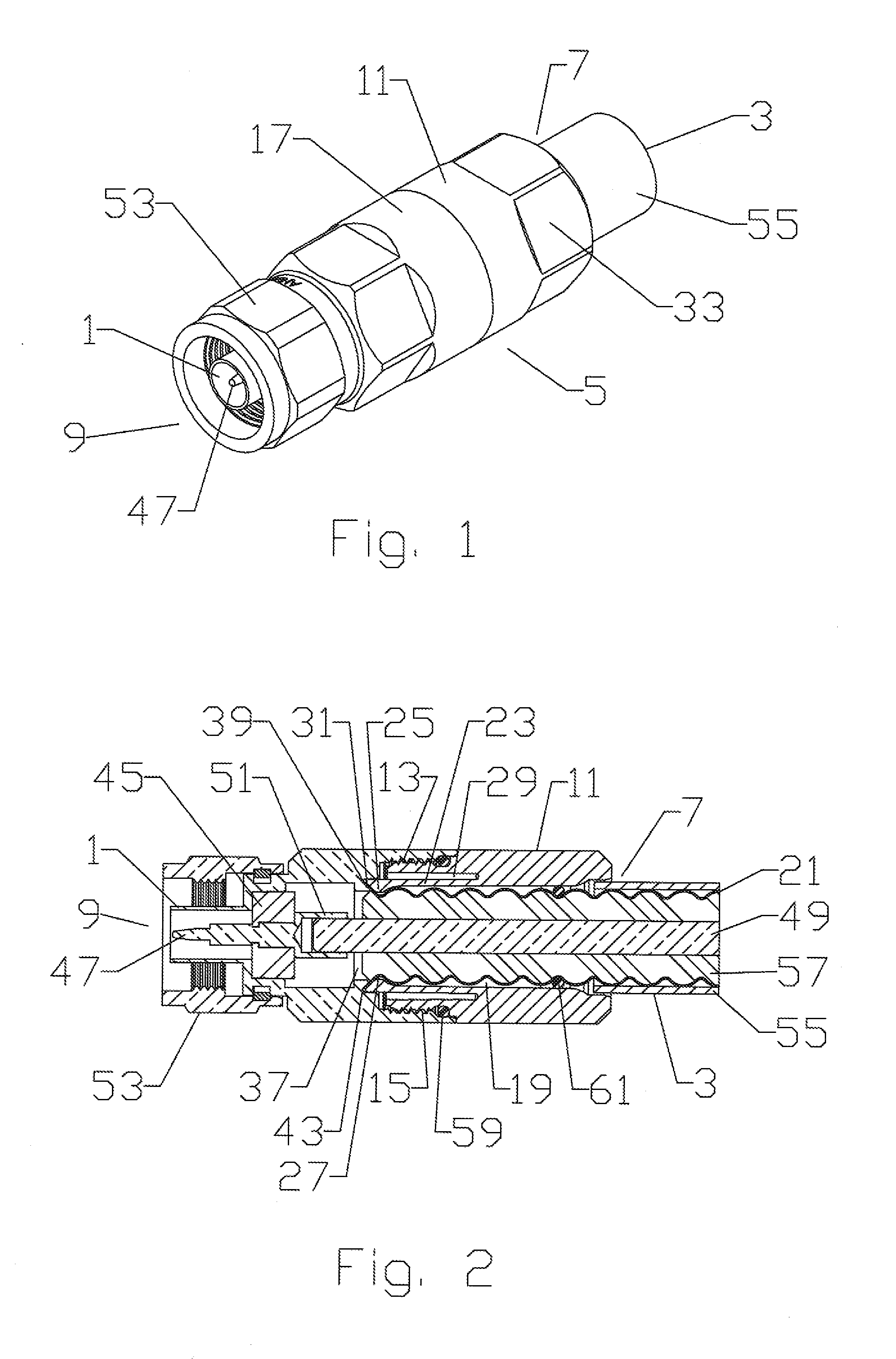
[0021]The spring finger nut 11 may be formed from a polymeric material such as polybutylene terephthalate (PBT) plastic resin. The PBT or other selected polymeric material may be injection molded and or machined. Carbon black or the like may be added to the PBT or other selected polymeric material to improve a UV radiation resistance characteristic of the polymeric material. Because the polymeric material can be expected to have an increased flexibility characteristic compared to the prior brass or the like metal material of the same thickness, the number of sections applied to form the individual spring fingers may be reduced, further reducing both injection mold cost and mold separation problems during manufacture. For example, a total of four or less individual spring finger(s) 23 may be applied, the width of the selected number of spring fingers preferably adjusted to surround the nut bore.
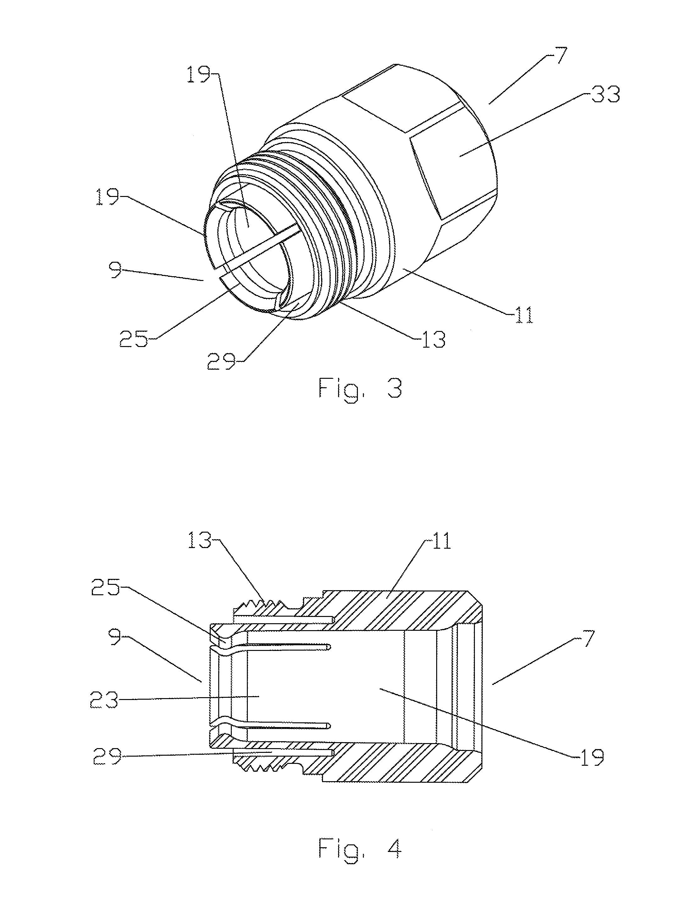
[0023]Because injection molding of the spring finger nut 11 allows the annular groove 29 to be easily formed with a considerable depth, for example extending towards the cable end 7 to the base of the spring finger(s) 23, the deflection space is provided without requiring location of the outer diameter thread 13 towards the cable end of the spring finger nut 11. Therefore, the length of the body 17 and thereby the amount of metal material required to position the inner diameter thread 15 to mate with the outer diameter thread 13 is significantly reduced.
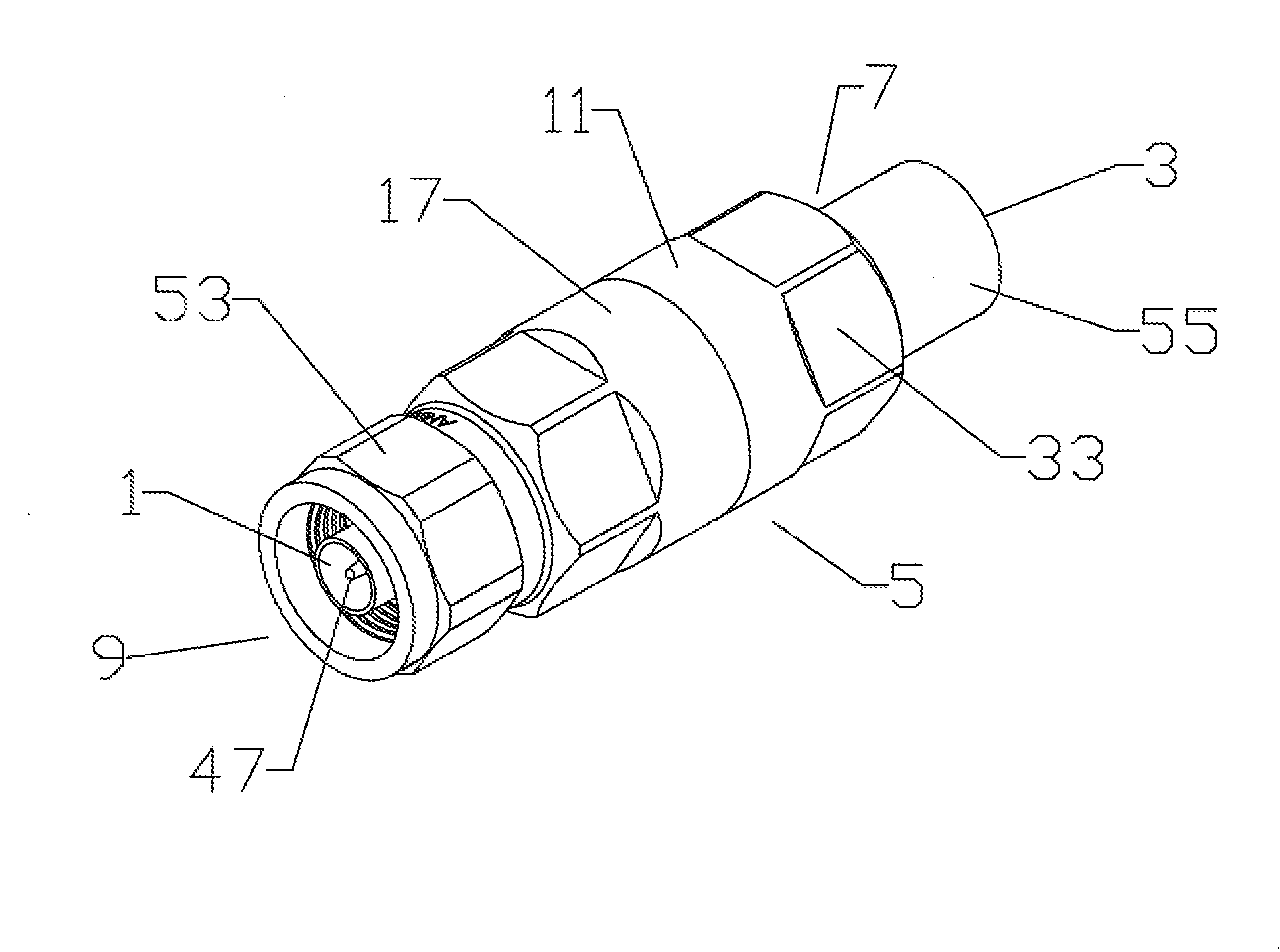
[0024]As the outer conductor 21 is inserted into the cable end 7 of the nut bore 19, the spring finger(s) 23 momentarily deflect into the annular groove 29 to allow the inward projecting bead(s) 25 to pass over the lead corrugation 31 of the outer conductor 21 and into the corrugation trough 27 immediately behind it. Flat(s) 33 or other form of hand or tool gripping surface may be formed in the outer diameter of the spring finger nut 11 for ease of threading the body 17 onto the spring finger nut 11.
[0032]The invention provides an environmentally sealed connector 1 with improved cost efficiency and installation characteristics. Use of the polymeric material for the spring finger nut 11 reduces costs and overall connector weight, without impacting the electrical characteristics of the connection between the outer conductor and the body 17. The presence of the annular groove 29 shortens the required length of the body 17, further reducing metal material requirements and the overall weight of the connector. Because the factory pre-assembled connector 5 does not require any disassembly or other preparation before mounting upon a coaxial cable 3, drop hazard is reduced and the opportunity for losing or damaging an essential part of the connector 5 has been eliminated.TABLE OF PARTS

Problems solved by technology

A significant cost factor of this design is both the metal material and the numerous metal machining steps required during manufacture.
Therefore, the connector is incompatible with annular corrugated solid outer conductor coaxial cable, is expensive to manufacture and time consuming to install.
Because cable connection may occur in hazardous locations such as high atop an antenna tower, separation of the connector and any additional required assembly operations creates a significant drop hazard and or installation burden for the installation personnel.

Method used


Image

  • Annular Corrugated Coaxial Cable Connector with Polymeric Spring Finger Nut
  • Annular Corrugated Coaxial Cable Connector with Polymeric Spring Finger Nut
  • Annular Corrugated Coaxial Cable Connector with Polymeric Spring Finger Nut

Examples


Embodiment Construction

[0017]The inventor has recognized that a spring finger nut element of a connector according to the invention may be formed from a polymeric material via injection molding to eliminate the numerous required metal machining steps and significantly reduce materials costs and component weight. Although the connector body of a connector according to the invention may also be formed partially or completely from polymeric material, for example via overmolding or application of an internal conductive coating or separate internal conductive element, where only the metal spring finger nut is formed from polymeric material, the requirement for and associated complexities of an additional internal outer conductor conductive structure is eliminated.

[0018]The invention will be described in detail with respect to FIGS. 1-7, demonstrating an exemplary embodiment having a standard Type-N connector interface 1 for use with an annular corrugated solid outer conductor coaxial cable 3. One skilled in th...


PUM

PropertyMeasurementUnit
outer diameteraaaaaaaaaa
inner diameteraaaaaaaaaa
diameteraaaaaaaaaa

Abstract

An annular corrugated solid outer conductor coaxial cable electrical connector with an integral spring finger nut telescopically coupled via threads to the cable end of a body. A nut bore in the spring finger nut dimensioned to receive the outer conductor therethrough. A plurality of spring fingers around the periphery of the interface end of the nut bore, projecting towards the interface end, the spring fingers provided with an inward projecting bead at the interface end. the interface end of the spring fingers initially deflectable into an annular groove open to the interface end between the spring fingers and an outer diameter of the spring finger nut.

Description

BACKGROUND OF INVENTION[0001]1. Field of the Invention[0002]The invention relates to an electrical connector. More particularly the invention relates to a lightweight and cost efficient annular corrugated coaxial cable electrical connector with a polymeric material coupling nut.[0003]2. Description of Related Art[0004]Connectors for corrugated outer conductor cable are used throughout the semi-flexible corrugated coaxial cable industry. Connectors for solid outer annular corrugated outer conductor coaxial cable, for example as disclosed in U.S. Pat. No. 4,046,451, issued Sep. 6, 1977 to Juds et al, attach using mechanical compression between a body and a spring finger nut having spring fingers that clamp a leading edge of the outer conductor against an angled contact surface of the connector body. The spring fingers are outward deflectable, allowing the spring finger nut to be placed over the cable end, positioning the spring finger ends in a trough behind the lead corrugation peak ...

Claims


Application Information

Patent Timeline
Patent Type & Authority Applications(United States)
IPC IPC(8): H01R9/05
CPCH01R24/564Y10T29/49123H01R2103/00H01R9/05
Inventor WLOS, JAMES
Owner ANDREW LLC
Why Eureka
Eureka Blog
Learn More