
Continuous conductive materials for electromagnetic shielding

a technology of electromagnetic shielding and conductive materials, applied in the field of medical devices, can solve the problems of adverse effects on other limitations of exposing implanted leads of medical devices to electromagnetic fields and/or radio-frequency energy, wrong therapy being administered to patients at that time or in the future, etc., and achieves the effects of high conductive surface area, small size and effective combination

Active Publication Date: 2008-08-14
MEDTRONIC INC
View PDF101 Cites 94 Cited by
  • Summary
  • Abstract
  • Description
  • Claims
  • Application Information

AI Technical Summary

Benefits of technology

[0008]Embodiments of the invention relate to medical electrical leads having a conductor assembly covered by an insulating layer, and a shield covering positioned adjacent or proximate to at least a portion of the insulating layer in order to shield the conductor assembly from one or more electromagnetic fields. The shield covering is formed of a material that is electrically conductive, where the material is in a wrapped or woven form. The material is selected so as to have an effective combination of small size and high conductive surface area, e.g., as opposed to metal wire or coatings thinner than metal wire. As such, the shield covering exhibits sufficient conductivity in the presence of one or more high frequency electromagnetic fields so that interference to the operation of the conductor assembly is minimized. The material can have a coating formed of one or more metals. The material can include carbon. In turn, the carbon can be formed of one or more of carbon fiber, carbon nanofiber, and single or multi-walled carbon nanotube.

Problems solved by technology

It is well known that, if not shielded sufficiently, the implanted leads of medical devices can be adversely affected when a patient is exposed to alternating electromagnetic fields.
Because the tissue area associated with electrode contact may be very small, the current densities may be high, which can result in tissue heating that may cause damage.
There can be other limitations associated with exposing implanted leads of medical devices to electromagnetic fields and / or radio-frequency energy if the leads are not sufficiently shielded therefrom.
The medical device, as should be appreciated, can sense the imposed voltage on the lead, and in turn, may cause the device to respond inappropriately, resulting in the wrong therapy being administered to the patient at that time or in the future.
For example, with respect to cardiac IMDs, inappropriate therapy modification may be one response of the IMD, which can involve changing the rate or thresholds associated with pacing pulses.
These MRI systems can be used to give valuable diagnostic information, but also subject the patient to significant alternating electromagnetic fields and / or radio-frequency energy, which may result in one or more of the undesirable effects described above with respect to IMDs or medical devices using implanted leads.
While the wire lead coverings have been used to reduce the effects of electromagnetic radiation, the lead coverings have been found to present certain limitations, e.g., with respect to minimum sizes that can achieved, high production costs, etc.

Method used


Image

  • Continuous conductive materials for electromagnetic shielding
  • Continuous conductive materials for electromagnetic shielding
  • Continuous conductive materials for electromagnetic shielding

Examples


Embodiment Construction

[0023]The following detailed description should be read with reference to the drawings, in which like elements in different drawings are numbered identically. The drawings depict selected embodiments and are not intended to limit the scope of the invention. It will be understood that embodiments shown in the drawings and described below are merely for illustrative purposes, and are not intended to limit the scope of the invention as defined in the claims.

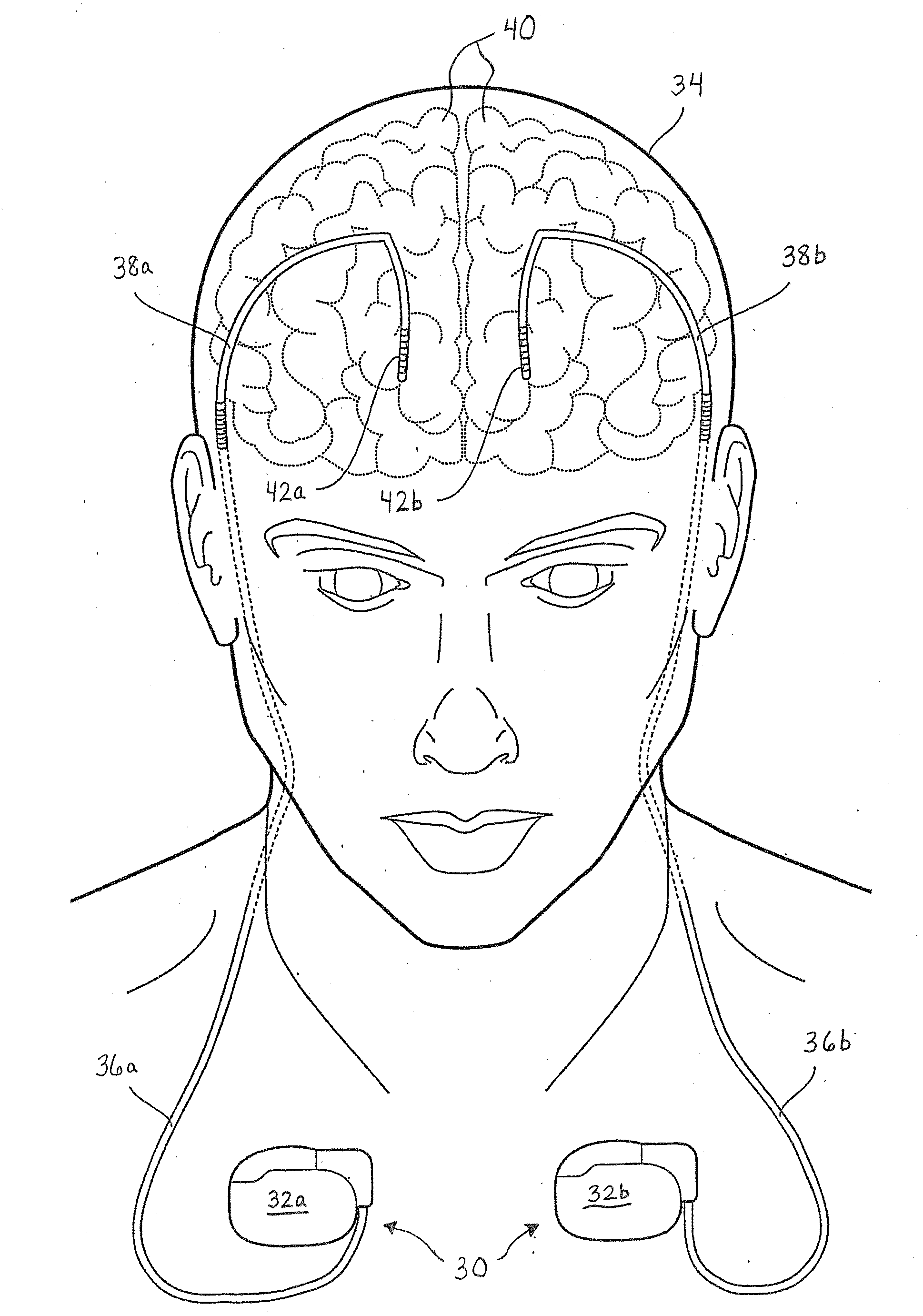
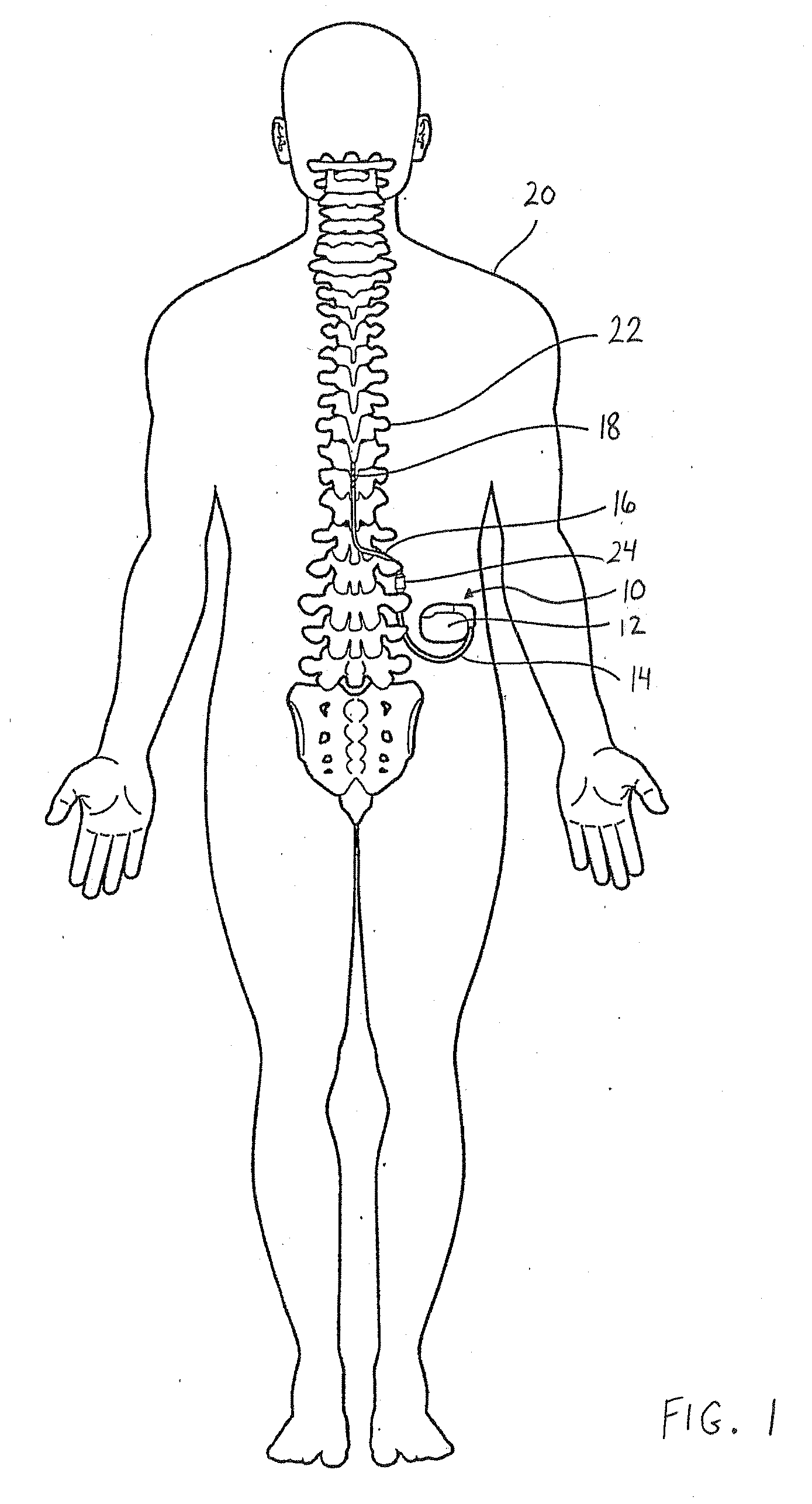
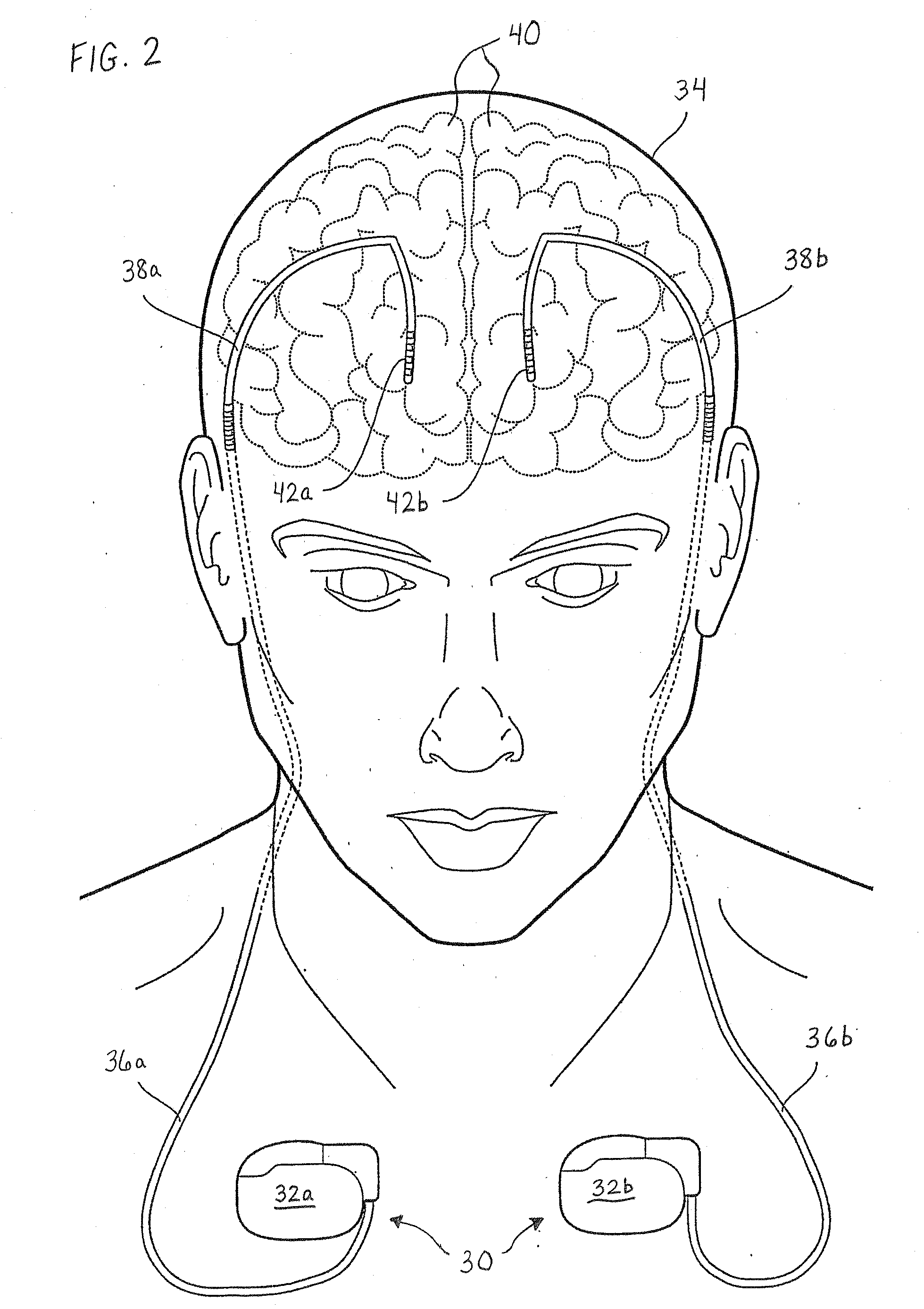
[0024]Embodiments of the invention relate to medical devices, and specifically relate to shield coverings for leads extending between the devices and the patient. Embodiments described and illustrated herein pertain to implantable medical devices (IMDs); however, the invention can extend to any lead-bearing medical device, whether implantable or not. Furthermore, while the embodiments provided herein relate to certain IMDs, it should be appreciated that such embodiments are exemplary in nature. As such, the invention is not limited ...


PUM


Abstract

A medical electrical lead having a conductor assembly covered by an insulating layer, and a shield covering positioned adjacent or proximate to at least a portion of the insulating layer in order to shield the conductor assembly from one or more electromagnetic fields. The shield covering is formed of a material that is electrically conductive, where the material is in a wrapped or woven form. The material is selected so as to have an effective combination of small size and high conductive surface area, e.g., as opposed to metal wire or coatings thinner than metal wire. As such, the shield covering exhibits sufficient conductivity in the presence of one or more high frequency electromagnetic fields so that interference to the operation of the conductor assembly is minimized. The material can have a coating formed of one or more metals. The material can include carbon. In turn, the carbon can be formed of one or more of carbon fiber, carbon nanofiber, and single or multi-walled carbon nanotube.

Description

FIELD[0001]The present invention relates generally to medical devices, and, more particularly, to reducing the effects of electromagnetic radiation on such medical devices.BACKGROUND[0002]Since their earliest inception, implantable medical devices (IMDs) have continually been advanced in significant ways. Today, IMDs include therapeutic and diagnostic devices, such as pacemakers, cardioverter / defibrillators, hemodynamic monitors, neurostimulators, and drug administering devices, as well as other devices for alleviating the adverse effects of various health ailments.[0003]As is known, modern electrical therapeutic and diagnostic devices for the heart and other areas of the body generally include an electrical connection between the device and the body. This connection is usually provided by at least one medical electrical lead. For example, a neurostimulator delivers mild electrical impulses to neural tissue using one or more electrical leads. In turn, such neurostimulation often res...

Claims


Application Information

Patent Timeline
Patent Type & Authority Applications(United States)
IPC IPC(8): A61N1/04
CPCA61N2001/086A61N1/0551A61N1/086A61N1/3718
Inventor LI, BERNARDCAI, CHADCHEN, XINGFU
Owner MEDTRONIC INC
Learn More