Method and apparatus for manufacturing honeycomb compact-body molding die

a technology of compact body and molding die, which is applied in the manufacture of electrical-based machining electrodes, manufacturing tools, other domestic articles, etc., can solve the problems of sidewise electrical discharge, weakening of the apical end of the electrode, and reducing the precision of the slit recess being processed, so as to reduce the occurrence of electrode deformation, improve the precision, and reduce the siz

Inactive Publication Date: 2008-08-21
DENSO CORP
View PDF0 Cites 101 Cited by
  • Summary
  • Abstract
  • Description
  • Claims
  • Application Information

AI Technical Summary

Benefits of technology

[0011]The present invention has been completed with a view to addressing the above issues and has an object to provide a method and apparatus for manufacturing a honeycomb structure-body molding die which can suppress the occurrence of deformation of an electrode during an electrical discharge processing while making it possible to process slit recesses each in a finely small size with increased precision.

Problems solved by technology

However, in such a case, an apical end of the electrode becomes thin to be weak against stress applied in a lateral direction.
In addition, the wearing of the electrode results in the occurrence of sidewise electrical discharge.
This causes a deformation or damage to occur on the electrode, resulting in an issue with a drop in precision of the slit recesses being processed.
However, with the electrode made thin, the electrode has low rigidity and is weak against lateral load, causing the electrode to be deformed when the sidewise electric discharge occurs.

Method used


Image

  • Method and apparatus for manufacturing honeycomb compact-body molding die
  • Method and apparatus for manufacturing honeycomb compact-body molding die
  • Method and apparatus for manufacturing honeycomb compact-body molding die

Examples


embodiment

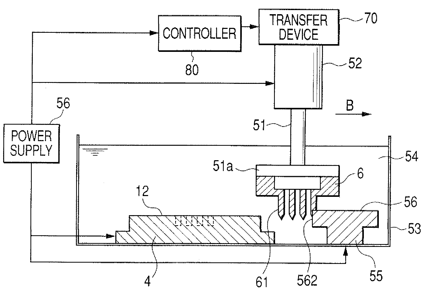
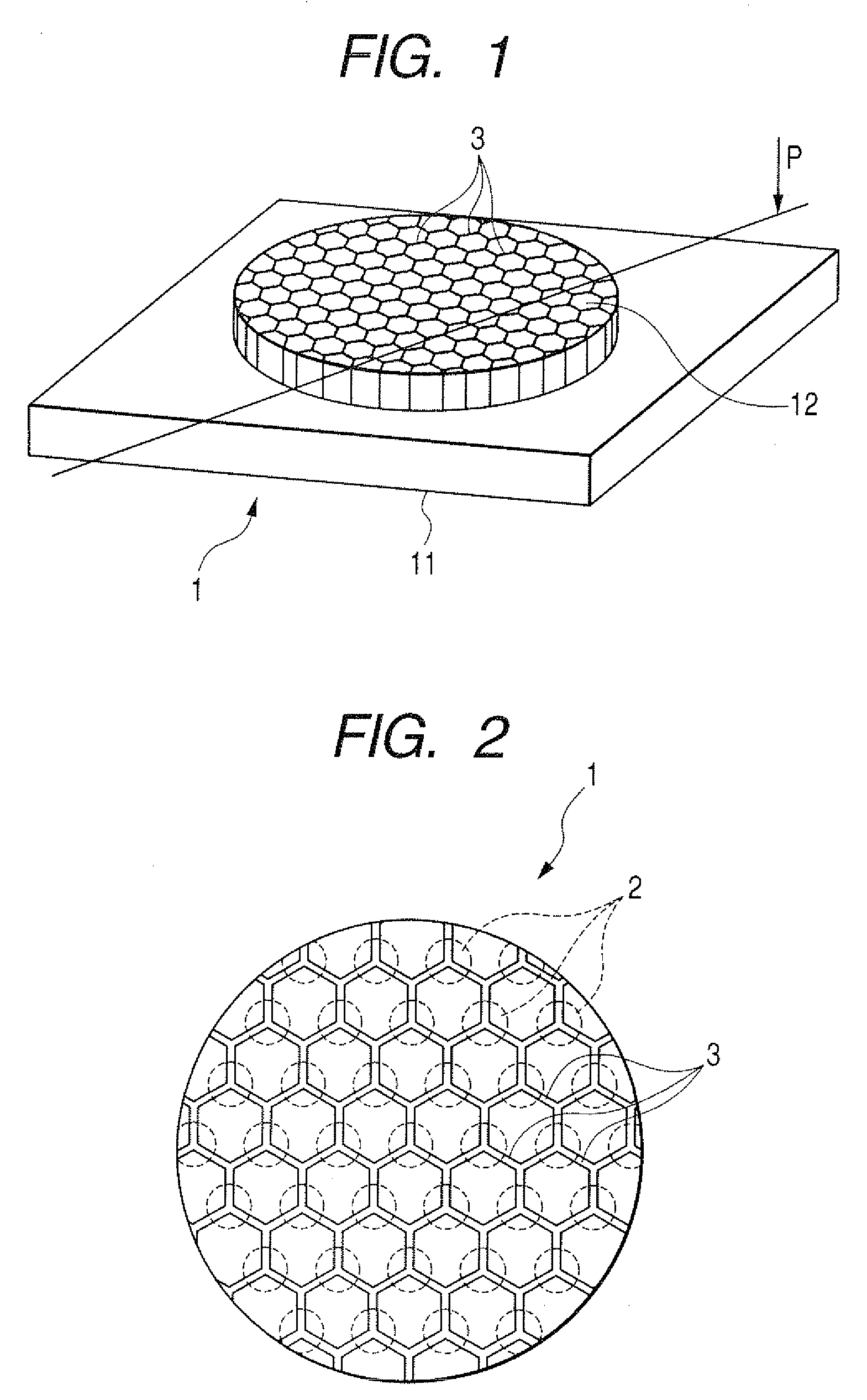
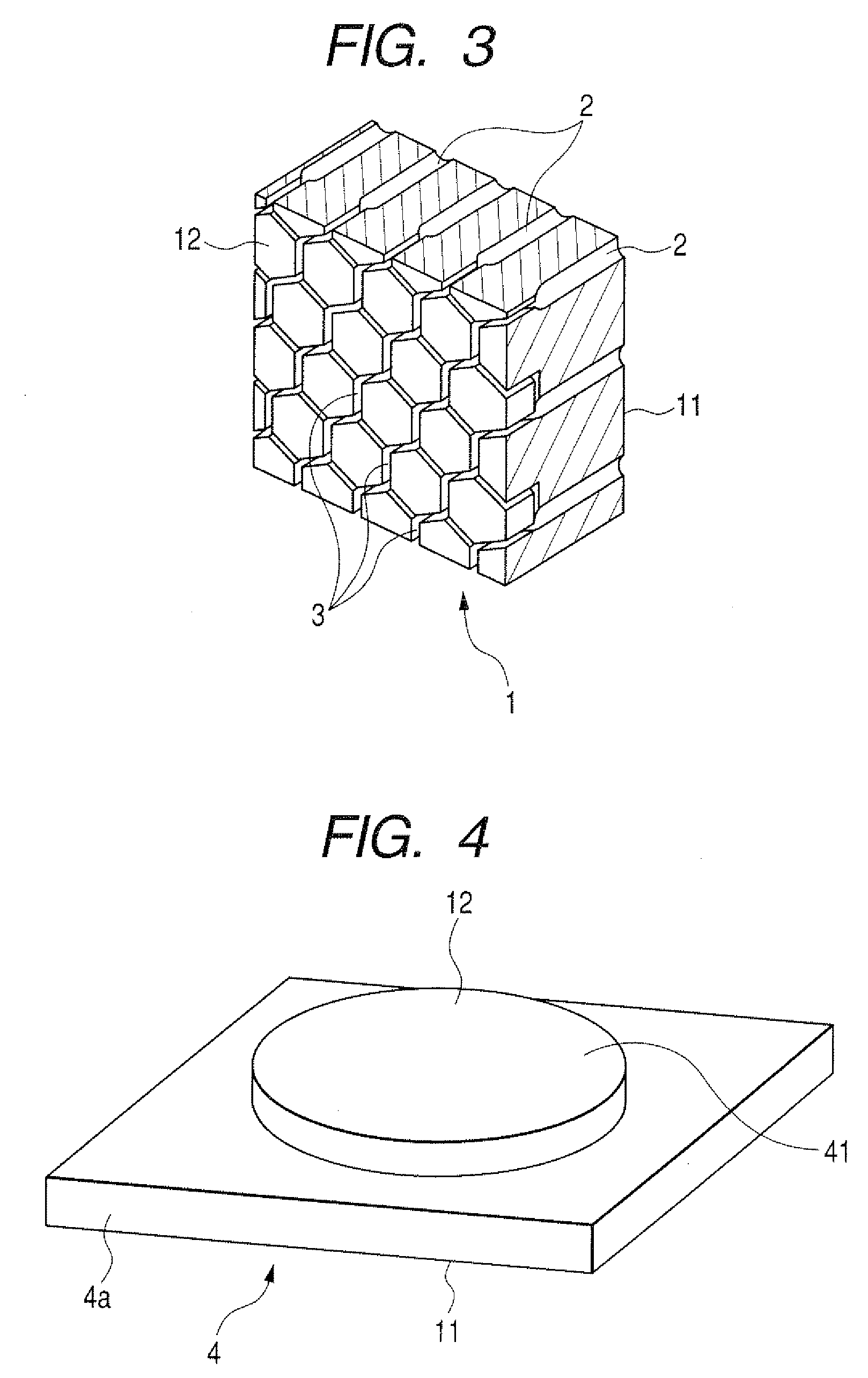
[0028]With the method of manufacturing a honeycomb compact-body molding die according to the present invention, as set forth above, the recess processing step is conducted using an electrode having electrode segments, formed in a lattice structure corresponding to the shapes of the slit recesses, each of which has a wall thickness of 0.1 mm or less.

[0029]With the electrode segments each having the wall thickness exceeding 0.1 mm, it becomes difficult to form the slit recesses in finely small sizes suited for a specified application to a honeycomb compact-body molding die.

[0030]Further, the electrode has an apical electrical discharge surface that is parallel to the recess forming surface of the molding die.

[0031]Furthermore, the electrode may be preferably made of raw material such as copper tungsten (CuW).

[0032]Further, in the method of manufacturing a honeycomb compact-body molding die, an electrical discharge machining step and apical end cut-off processing step are alternately e...


PUM

PropertyMeasurementUnit
wall thicknessaaaaaaaaaa
lengthaaaaaaaaaa
lengthaaaaaaaaaa

Abstract

A method and apparatus for manufacturing a honeycomb compact-body molding die having material feed bores for supplying material therethrough and slit recesses formed in a polygonal lattice pattern to mold the material in a compact body with a honeycomb shape are disclosed. The slit recesses are formed on a recess forming surface of the molding die using an electrode having electrode segments, formed in a lattice pattern corresponding to shapes of the slit recesses each of which has a wall thickness of 0.1 mm or less, to generate an electrical discharge between the molding die and the electrode to form the slit recess on the molding die. When the electrode is worn by a given amount, an apical end cut-off processing step is executed to cut off an apical end of the electrode using a dress plate to expose a new apical end formed with an electrical discharge surface.

Description

CROSS REFERENCE TO RELATED APPLICATIONS[0001]This application is related to Japanese Patent Application No. 2007-41089, filed on Feb. 21, 2007, the content of which is hereby incorporated by reference.BACKGROUND OF THE INVENTION[0002]1. Technical Field of the Invention[0003]The present invention relates to methods and apparatuses for manufacturing honeycomb structure-body molding dies and, more particularly, to a method and apparatus for manufacturing a honeycomb structure-body molding die for use in molding a honeycomb structure body.[0004]2. Description of the Related Art[0005]Honeycomb compact bodies, used for exhaust gas purifying devices of motor vehicles, have been made of, for instance, ceramics having a principal component of cordierite or the like. The honeycomb compact bodies have been manufactured by extrusion molding a material, containing ceramics raw material, using honeycomb structure-body molding dies (hereinafter suitably referred to merely as “molding dies”). Each ...

Claims


Application Information

Patent Timeline
Patent Type & Authority Applications(United States)
IPC IPC(8): B21C25/02B23H1/04B23P15/24B26D7/00B29C48/11
CPCB23H1/04B23H9/00B23H2200/30B23P15/243Y10T29/49995B29C47/0028B29C47/12B29L2031/60Y10T29/49996B28B2003/203B29C48/11Y10T83/0581Y10T83/8748Y10T83/0304
Inventor SHINYA, KIYOFUMIKATSURA, ISAOOONISHI, MAMORU
Owner DENSO CORP
Why Eureka
Try Eureka