Plate Heat Exchanger

Active Publication Date: 2008-08-21
ALFA LAVAL CORP AB
View PDF13 Cites 32 Cited by
  • Summary
  • Abstract
  • Description
  • Claims
  • Application Information

AI Technical Summary

Benefits of technology

[0010]The object of the present invention is to eliminate or at least alleviate the above referenced drawbacks and to provide a plate heat exchanger, which is easy and cost effective to manufacture and in which the

Problems solved by technology

A problem which arises in connection with a refrigeration system of the above referenced type, is that refrigerant entering the inlet channel of the plate heat exchanger is not evenly distributed to the different evaporation flow paths in the interspaces between the heat transfer plates.
Uneven distribution of refrigerant to the different evaporation flow paths in the plate heat exchanger results in ineffective use of parts of the plate heat exchanger.
Moreover, the refrigerant may become unnecessarily overheated.
Furthermore, some channels may be flooded by liquid refrigerant and there is also a risk that some liquid may be present at the outlet.
Plate heat exchangers provided with restriction means of the above mentioned kind give rise to several difficulties during the manufacture thereof.
The use of separate rings or washers has resulted in problems with the location of the rings or washers in the correct positions when a plate heat exchanger is assembled.
A restrictions means in the form of a pipe has the disadvantage that it must have a length adapted to the number of heat transfer plates in

Method used


Image

  • Plate Heat Exchanger
  • Plate Heat Exchanger
  • Plate Heat Exchanger

Examples


Embodiment Construction

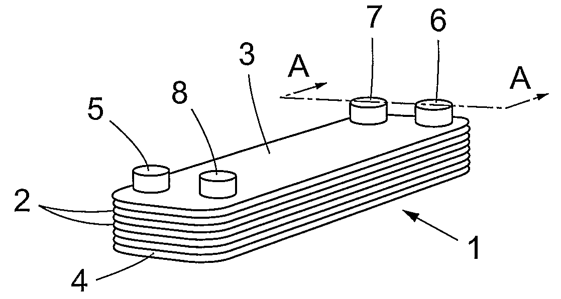
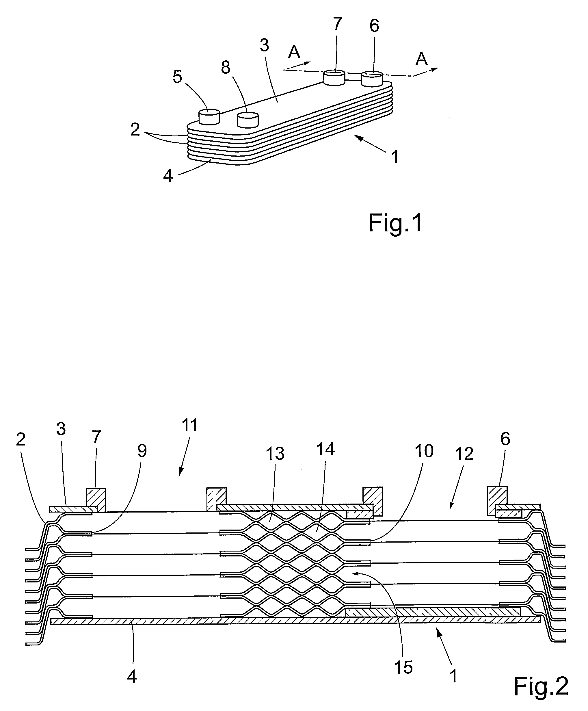
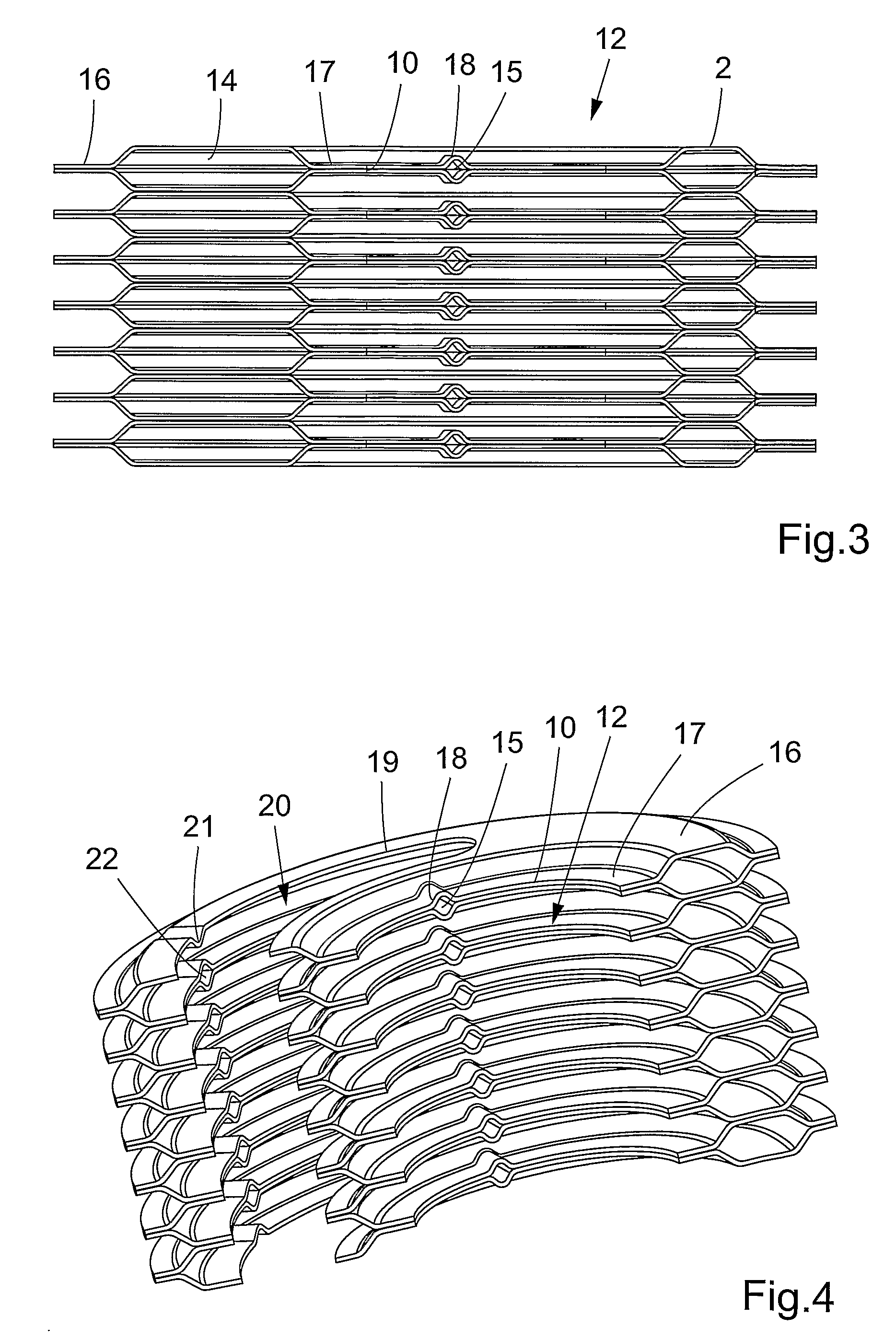
[0032]In FIG. 1 a conventional single circuit plate heat exchanger 1 is shown which is designed to be used as an evaporator in a cooling system. The plate heat exchanger 1 comprises a number of heat transfer plates 2, which are provided on top of each other between the upper, outer cover plate 3 and the lower, outer cover plate 4, and which are permanently joined by brazing, gluing or welding. Preferably, the heat transfer plates 2 are provided with a corrugation pattern of parallel ridges extending such that the ridges of adjacent heat transfer plates 2 cross and abut against each other in the plate interspaces. Furthermore, the plate heat exchanger 1 has first and second inlets 5 and 6, and first and second outlets 7 and 8, for two heat exchange fluids.

[0033]The number of heat transfer plates may of course vary with respect to the desired heat transfer capacity of the plate heat exchanger. During joining by means of brazing a suitable number of heat transfer plates are piled on ea...


PUM


Abstract

The invention relates to a plate heat exchanger (1) having a package of heat transfer plates (2), which are provided with through inlet ports (10) forming an inlet channel (12) through the package, and between the heat transfer plates arranged sealing means, which together with the heat transfer plates in every other plate interspace delimit a first flow passage (14) for one fluid and in each of the remaining plate interspaces delimit a second flow passage (13) for a second fluid, wherein the inlet channel (12) communicates with each first flow passage (14) by way of a first inlet passage (15), and is sealed from communication with each second flow passage by the sealing means.

Description

FIELD OF THE INVENTION[0001]The present invention relates to plate heat exchanger comprising a package of heat transfer plates, which are provided with through inlet ports forming an inlet channel through the package, and between the heat transfer plates arranged sealing means, which together with the heat transfer plates in every other plate interspace delimit a first flow passage for one fluid and in each of the remaining plate interspaces delimit a second flow passage for a heating fluid, wherein said inlet channel communicates with each first flow passage by way of an inlet passage, and is sealed from communication with each second flow passage by said sealing means.BACKGROUND OF THE INVENTION[0002]Plate heat exchangers are frequently used as evaporators for evaporation of refrigerants circulated in refrigeration systems. Normally, such a refrigeration system comprises a compressor, a condenser, an expansion valve and an evaporator, all of which are coupled in series. In a plate...

Claims


Application Information

Patent Timeline
IPC IPC(8): F28D9/00
CPCF28D9/005F28F2240/00F28F9/026F28D2021/0071F28F27/02F28D9/00
Inventor BERTILSSON, KLASPAVAN, MARCELLOZORZIN, ALVAROSARTORI, LORIS
Owner ALFA LAVAL CORP AB
Why Eureka
Try Eureka