Bonding Tool

a technology of bonding tools and tabs, which is applied in the direction of manufacturing tools, soldering devices, auxilary welding devices, etc., can solve the problems of reducing the amount of gold required for bonding, reducing the time-consuming process of single-point bonding, and shortening the production cycle time. , to achieve the effect of accelerating the tab bonding process

Inactive Publication Date: 2008-08-21
REIBER STEVEN F
View PDF99 Cites 16 Cited by
  • Summary
  • Abstract
  • Description
  • Claims
  • Application Information

AI Technical Summary

Benefits of technology

[0014]Some embodiments of the present invention advantageously provides for the use of multi-head-contact and multi-contact TAB bonding tools to accelerate the TAB bonding process. An operator may complete an assembly process through the use of, for example, two or three bonding operations instead of the usual four or six bonding operations. Further embodiments of the present invention advantageously provides for an multi-head-contact and multi-contact TAB bonding tools that may be made from a uniform extrinsic material tha

Problems solved by technology

Single-point bonding is a more time-consuming process than the second methodology—gang bonding.
The use of bond pads over all of the die instead of the die periphery increases I/O count, reduces the amount of gold required for bonding, and shortens pro

Method used


Image

  • Bonding Tool
  • Bonding Tool
  • Bonding Tool

Examples


Embodiment Construction

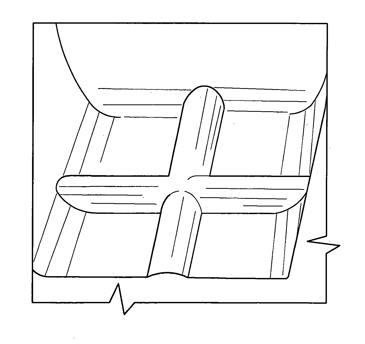
[0020]FIG. 3 illustrates a single point Tape Automated Bonding (TAB) tool utilizing a double cross groove according to an embodiment of the present invention and as may be utilized in a multi-head-contact or multi-contact TAB bonding tool. Reference to a double cross groove is not meant to limit the scope of the present TAB tool in that other groove configurations are known in the art and may be utilized. These configurations include but are not limited to a single cross groove, a single point, a protruding ‘V,’ and the aforementioned waffle.

[0021]An exemplary multi-head-contact or multi-contact TAB tool may be one-half to three inches (12-80 mm) long and approximately one-sixteenth to one-eighth of an inch (1.6 to 3 mm) in diameter. The tool may be integrated with a transducer; the diameter, therefore, need not be determinative. The bonding tool tip itself is, in some embodiments, 3 to 10 mils (0.08 to 0.25 mm) square. In another embodiment, a multi-contact bonding tool may be appr...


PUM

PropertyMeasurementUnit
Electrical resistanceaaaaaaaaaa
Electrical conductivityaaaaaaaaaa
Concentrationaaaaaaaaaa

Abstract

Means to increase the UPH of TAB bonding on an HSA manufacturing line to allow a higher UPH to keep cost down and also allow the use of one or more grounds to be add to an HSA to help control ESD without lowering the UPH or redesigning the lines through the use of a multi-head contact TAB bonding tool as described herein A bonding tool for use in tape automated bonding (TAB) is provided that is for multi-contact. The multi-contact TAB bonding tool is ESD safe so as not to damage a device being bonded.

Description

CROSS-REFERENCE TO RELATED APPLICATIONS[0001]The present application claims the priority benefit of U.S. provisional patent application No. 60 / 888,284 filed Feb. 5, 2007 and entitled “Multi-Head-Contact TAB Bonding Tool” and U.S. provisional patent application No. 60 / 888,517 filed Feb. 6, 2007 and entitled “Multi-Contact TAB Bonding Tool”; the present application is also a continuation-in-part of U.S. patent application Ser. No. 11 / 227,982 filed Sep. 14, 2005 and entitled “Multi-Head TAB Bonding Tool,” which claims the priority benefit of U.S. provisional patent application No. 60 / 610,847 filed Sep. 17, 2004 and entitled Multi-Head TAB Bonding Tool”; U.S. patent application Ser. No. 11 / 227,982 is also a continuation-in-part and claims the priority benefit of U.S. patent application Ser. No. 11 / 107,308 filed Apr. 15, 2005 and entitled “Flip Chip Bonding Tool and Ball Placement Capillary,” which is a continuation-in-part and claims the priority benefit of U.S. patent application Ser. ...

Claims


Application Information

Patent Timeline
IPC IPC(8): B23K37/00B23K31/00
CPCB23K2201/40B23K20/10B23K2101/40H01L2224/50
Inventor REIBER, STEVEN F.
Owner REIBER STEVEN F
Why Eureka
Try Eureka