Direction correcting apparatus, method thereof and movable radiation inspecting system

a direction correcting and inspection system technology, applied in the direction of optical radiation measurement, navigation instruments, instruments, etc., can solve the problems of increased manpower, health of the driver, collision of scanning vehicles with containers/load carrying vehicles, etc., to increase work efficiency and safety performance, easy assembly/disassembly, and simple structure

Active Publication Date: 2008-08-21
NUCTECH CO LTD +1
View PDF2 Cites 6 Cited by
  • Summary
  • Abstract
  • Description
  • Claims
  • Application Information

AI Technical Summary

Benefits of technology

[0040]Therefore, when direction deviation is being corrected, the inspecting system need not to be stopped, without manpower involvement, the control unit automatically completes the direction correction, increasing work efficiency and safety performance. In addition, the structure is simple with easy assembly / disassembly and reduced cost.
[0041]Additionally, according to a preferred embodiment of the invention, the distance between the moving device and the object to be inspected such as a container vehicle is controlled to a predetermined distance with the two photoelectric switches, so that the relative displacement of the moving device to the object to be inspected is avoided, otherwise the object to be inspected may be damaged by bumping.

Problems solved by technology

However, due to the uneven weight distribution of the scanning vehicle, the unevenness of the floor and inconsistency of gas pressures in the wheels etc., the moving direction of the scanning vehicle may be deviated from the predetermined direction parallel to the container / load carrying vehicle to be inspected after several scanning of the scanning vehicle.
If the deviation of the moving direction of the scanning vehicle is not corrected in time, it may occur that the scanning vehicle collides with the container / load carrying vehicle.
However, this leads to increase of manpower.
And since there is scattering rays during scanning, the health of the driver may be harmed.

Method used


Image

  • Direction correcting apparatus, method thereof and movable radiation inspecting system
  • Direction correcting apparatus, method thereof and movable radiation inspecting system
  • Direction correcting apparatus, method thereof and movable radiation inspecting system

Examples


second embodiment

[0088]The operation of the direction correcting apparatus according to the present invention will be described hereafter.

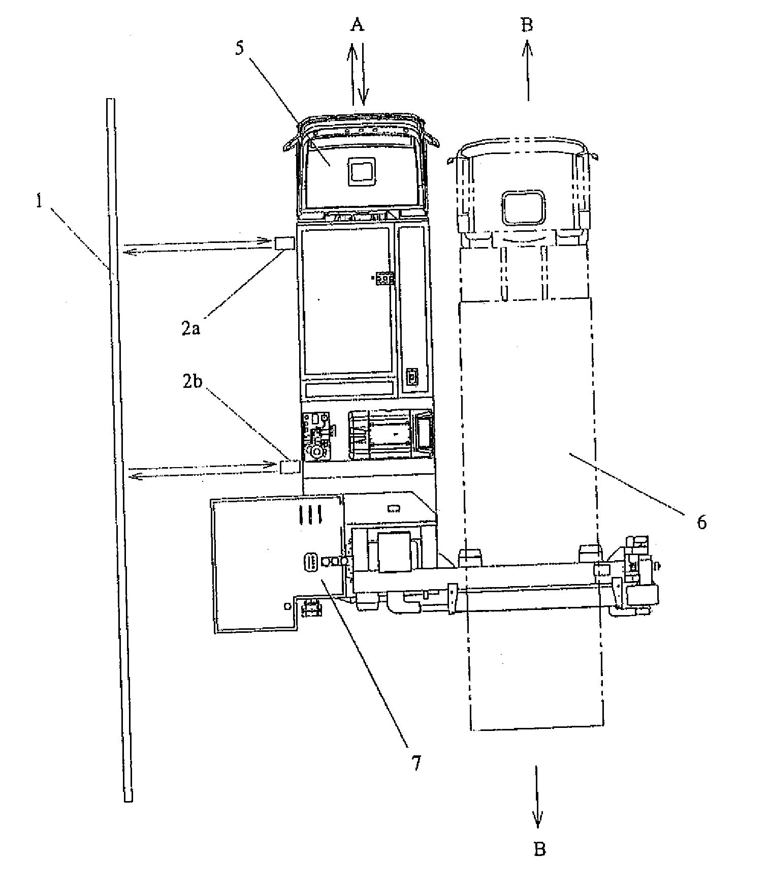
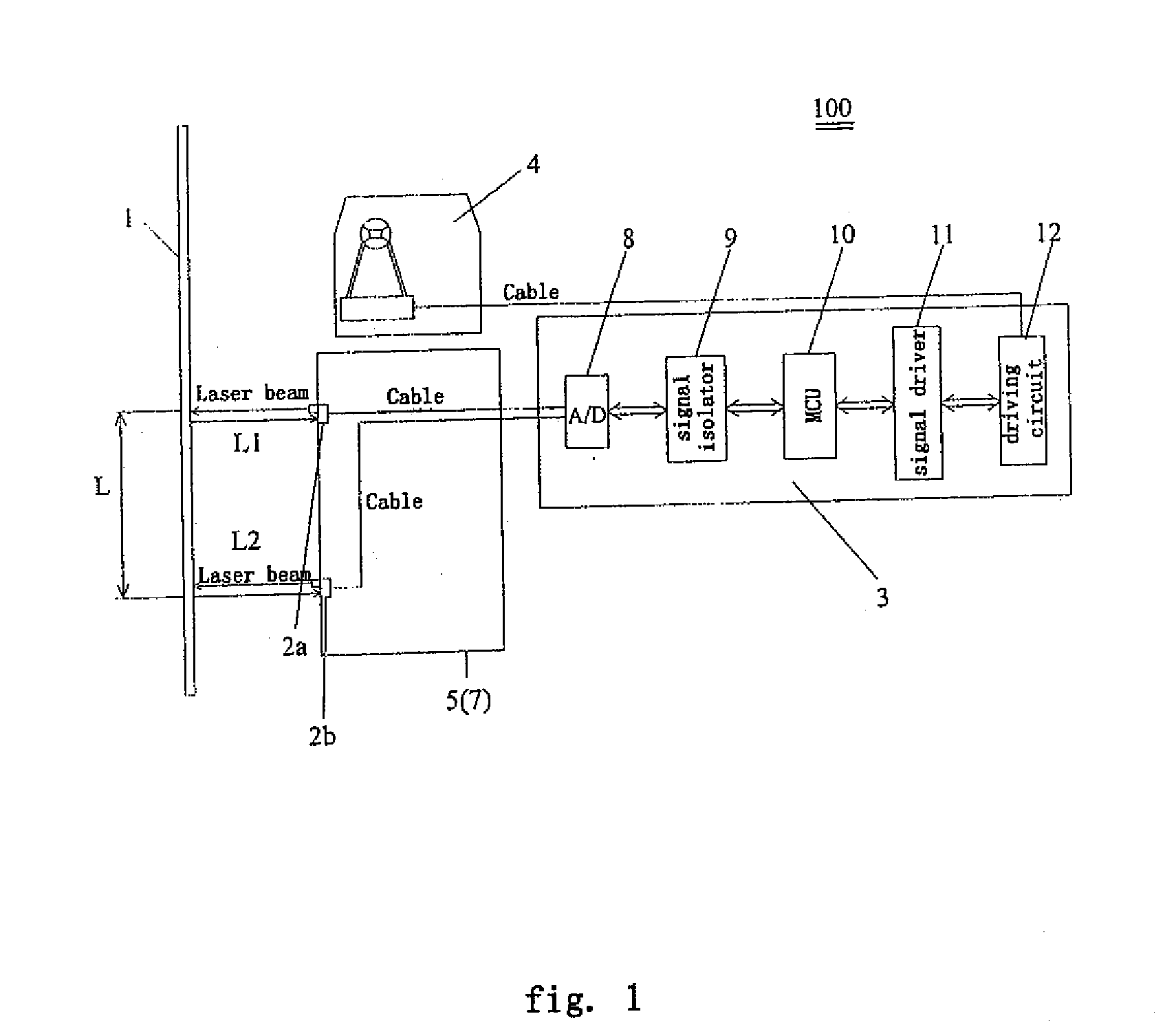
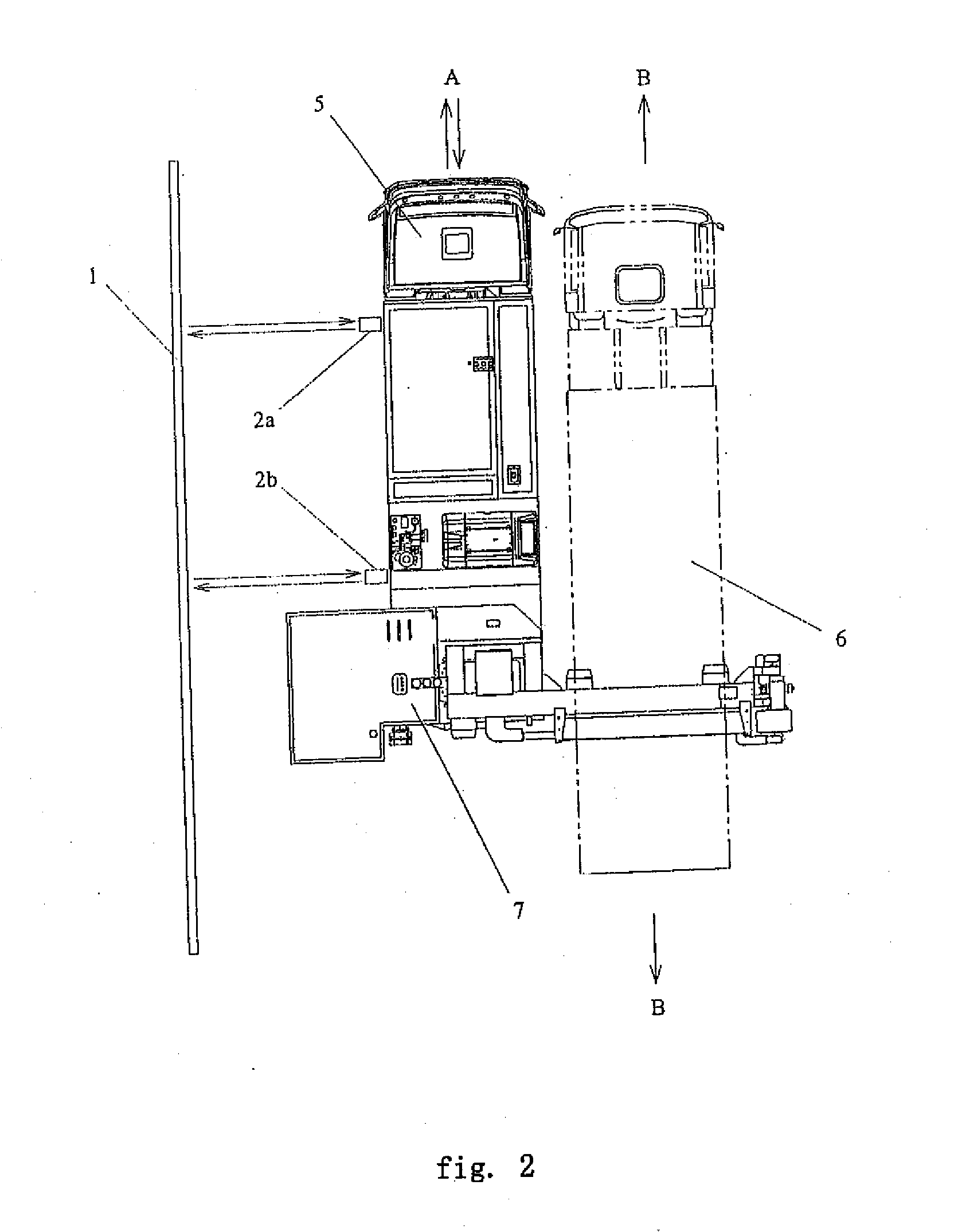
[0089]For example, when the moving device 5 is about to move for inspecting the vehicle 6 to be inspected, if the distance between the moving device 5 and the vehicle 6 to be inspected is larger than the predetermined distance, the first photoelectric switch 45 and the second photoelectric switch 46 both are switched off, thus it is determined by the control unit 3 that the moving device 5 is displaced leftwards in FIG. 4 with respect to the vehicle 6 to be inspected. Then, the control unit 3 generates corresponding driving signals for driving the direction control device 4, thus adjusting the moving direction of the moving device 5 and, further, adjusting the distance between the moving device 5 and the vehicle 6 to be inspected. When the control unit 3 receives the signals for indicating the first photoelectric switch 45 being switched on and the second photoele...

first embodiment

[0104]The operation of the actuator in the manner of a hydraulic cylinder or a gas cylinder is similar to those of the actuator in the present invention. For clarity purpose, the detailed description thereof is hereby omitted.

[0105]The second embodiment of the direction control device 4 will be described with reference to FIGS. 9-12. As shown in FIGS. 9, 10, FIG. 9 is a structural schematic plan of the direction control device 4 according to the second embodiment of present invention. And the FIG. 10 is the top view of FIG. 9. The direction control device 4 according to the second embodiment of the present invention comprises a steering wheel 13, a transmitting device 31 and a flexible traction member 32. The transmitting device 31 is driven by the control unit 3 (driving circuit 12), and the flexible traction member 32 turns around the steering wheel 13, and then both ends thereof twist to the transmitting device 31. Preferably, the flexible traction member 32 is a traction rope.

[0...


PUM

PropertyMeasurementUnit
driving currentaaaaaaaaaa
distanceaaaaaaaaaa

Abstract

The present invention discloses direction correcting apparatus and method thereof for a movable radiation inspecting system having a moving device. The direction correcting apparatus comprises: a direction detecting device for detecting a moving direction of the moving device and generating a detecting signal indicating the moving direction; a direction control device for controlling the moving direction of the moving device; and a control unit for calculating a deviation value between the moving direction and the predetermined direction based on the detected signal received from the direction detecting device, and the direction control device is driven according to the deviation value to correct the moving direction to the predetermined direction. The direction correcting apparatus according to the present invention can automatically control the movable radiation inspecting system to move linearly in a predetermined direction during working, which enhances automatic control degree, and has a simple structure with installing easily and reduced cost. And it also does not influence the normal running of the inspecting system on a road while not inspecting.

Description

FIELD OF THE INVENTION[0001]The present invention generally relates to a movable radiation inspecting system, a direction correcting apparatus for the movable radiation inspecting system and a direction correcting method thereof. More specifically, the invention relates to a vehicle carrying movable radiation inspecting system in which objects to be inspected, such as container / load carrying vehicle etc, are imaged by rays to inspect the objects by radiation. The invention also relates to a direction correcting apparatus for the vehicle carrying movable radiation inspecting system, in which the direction correcting apparatus automatically corrects a moving direction of a moving device of the movable radiation inspecting system to a predetermined direction when the moving direction departs away from the predetermined direction. The invention also relates to a direction correcting method for correcting a moving direction of the vehicle carrying movable radiation inspecting system.BACK...

Claims


Application Information

Patent Timeline
Patent Type & Authority Applications(United States)
IPC IPC(8): G01N23/00
CPCB62D1/00G05D2201/0213G05D1/024G01C21/00
Inventor XU, XININGSUN, SHANGMINYANG, ZHONGRONGPENG, HUAYANG, GUANGHU, HAIFENGLI, ZHIJUN
Owner NUCTECH CO LTD
Why Eureka
Try Eureka