Micro-Electro-Mechanical Transducers

a transducer and micro-electromechanical technology, applied in the field of micro-electromechanical devices, can solve the problems of poor device transmission and reception performance, high cost, and high difficulty in the process, and achieve the effect of enhancing high voltage protection and increasing conductivity

Active Publication Date: 2008-08-21
KOLO MEDICAL (SUZHOU) CO LTD
View PDF34 Cites 57 Cited by
  • Summary
  • Abstract
  • Description
  • Claims
  • Application Information

AI Technical Summary

Benefits of technology

[0066]Both the middle spring layer and the top plate may have many configurations. For example, the middle spring layer may be a contiguous layer placed over the standing feature of the substrate and extending over the sidewall to cover at least part of the cavity. The middle spring layer may include a first region and a second region, wherein the first region may have a low doped or intrinsic silicon material, and the second region a highly doped silicon material with increased conductivity. The two regions may form a PN junction to enhance high voltage protection. The top plate may have a thickness profile having at least two different thicknesses. The top plate may also include two different materials. For example, the first material may be a plurality of segments divided by separation trenches and the second material may connect the segments of the first material by spanning over the separation trenches. The second material may fill or partially fill the trenches.

Problems solved by technology

This process is fraught with difficulties and high expenses, not to mention the large input impedance mismatch problem presented by such elements to transmit / receiving electronics.
There are drawbacks in the cMUTs of the prior art structures and methods.
Many of these drawbacks relate to the fact that each addressable cMUT element is made of many individual cells and each cell has its cMUT membrane clamped or fixed on edges shared by the adjacent cells.
As a result both the device transmission and reception performance are poor.
(2) Surface areas occupied by the clamped areas (e.g., edges) and the walls or posts are non-active, thus reducing the device fill factor and the overall efficiency.
(3) Anchor areas introduce a parasitic capacitance which decreases the device sensitivity.
(4) The anchor pattern within the surface of the cMUT element may cause ultrasonic wave interference which limits the device bandwidth.
(5) The non-uniform displacement of the membrane may disturb the ultrasonic wave pattern.
For example, the non-uniform displacement may affect the ultrasonic beam pattern emitted from the transducer surface and also cause acoustic cross coupling through the transducer surface.
This causes phase differences of the membrane motion among different cells in the same cMUT element during operation.
As a result, the sum of the average displacement of the cMUT element may degrade dramatically.
This problem degrades the device performance especially when the cMUT works in a high quality factor (Q-factor) condition, for example in air.
(7) The acoustic energy can couple into the transducer substrate through supporting walls and cause undesired effects such as acoustic cross coupling between the cMUT elements.
An effort to reduce the cross-coupling through the substrate by introducing materials with desired acoustic properties may require occupation of extra space between elements.

Method used


Image

  • Micro-Electro-Mechanical Transducers
  • Micro-Electro-Mechanical Transducers
  • Micro-Electro-Mechanical Transducers

Examples


Embodiment Construction

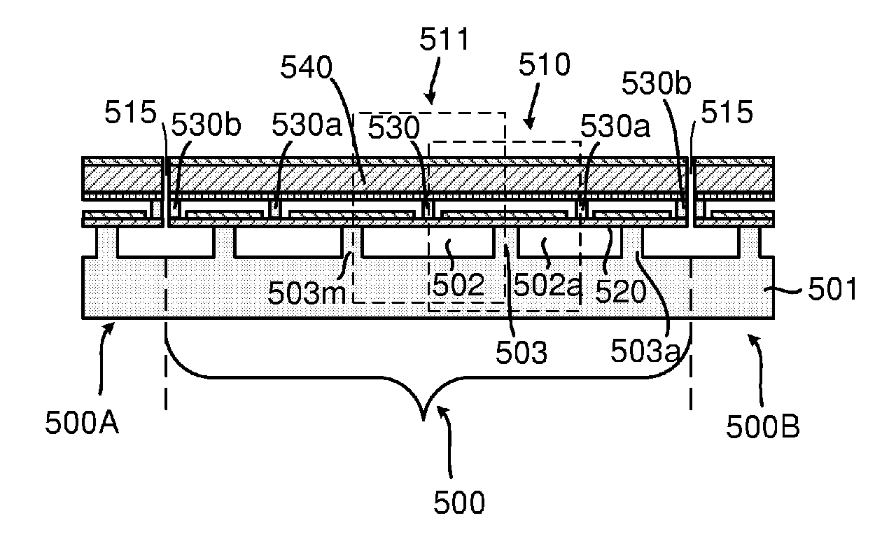
[0080]The micro-electro-mechanical transducer such as a capacitance micromachined ultrasonic transducer (cMUT) of the present invention will be described in detail along with the figures, in which like parts are denoted with like reference numerals or letters. The micro-electro-mechanical transducer may be fabricated using any suitable methods, particularly using the methods disclosed in several other patent applications identified herein, which are filed by a common applicant on even date.

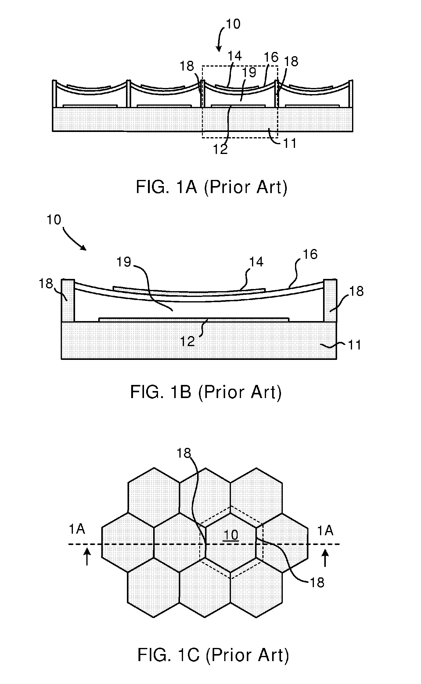
[0081]The invention has been described below with reference to specific embodiments. In most cases, a cMUT structure is used to illustrate the invention. It is appreciated, however, that the present invention is not limited to cMUTs. It will be apparent to those skilled in the art that various modifications may be made and other embodiments can be used without departing from the broader scope of the inventions. Therefore, these and other variations upon the specific embodiments are intended to be ...


PUM

PropertyMeasurementUnit
half wavelengthaaaaaaaaaa

Abstract

A micro-electro-mechanical transducer (such as a cMUT) is disclosed. The transducer has a substrate, a top plate, and a middle spring layer therebetween. The substrate and the middle spring layer define cavities therebetween sidewalled by standing features. The middle spring layer is anchored by the standing features to create cantilevers over the cavities to enable a vertical displacement of connectors placed on the middle spring layer. The connectors define a transducing space between the middle spring layer and the top plate. The top plate is transported by the vertical displacement of the connectors in a piston-like motion to change the transducing space and to effectuate energy transformation. Various configurations of cantilevers, including single cantilevers, back-to-back double cantilevers and head-to-head double cantilevers (bridges) are possible.

Description

[0001]This application claims priority from U.S. Provisional Application Ser. No. 60 / 682,619, filed May 18, 2005; Ser. No. 60 / 692,038, filed Jun. 17, 2005; Ser. No. 60 / 705,606, filed Aug. 3, 2005; and Ser. No. 60 / 744,242, filed Apr. 4, 2006, which applications are incorporated herein by reference in their entirety.[0002]This application further incorporates herein by reference in entirety the following:[0003]International Application (PCT), entitled THROUGH-WAFER INTERCONNECTION (Attorney Docket No. 03004.01), filed on even date with the present application by the common applicant;[0004]International Application (PCT), entitled METHODS FOR FABRICATING MICRO-ELECTRO-MECHANICAL DEVICES (Attorney Docket No. 03004.02), filed on even date with the present application by the common applicant; and[0005]International Application (PCT), entitled MICRO-ELECTRO-MECHANICAL TRANSDUCERS (Attorney Docket No. 03004.03), filed on even date with the present application by the common applicant.TECHNIC...

Claims


Application Information

Patent Timeline
Patent Type & Authority Applications(United States)
IPC IPC(8): H01L41/00
CPCB06B1/0292H01L2924/0002Y10T29/49005H01L2924/00
Inventor HUANG, YONGLI
Owner KOLO MEDICAL (SUZHOU) CO LTD
Why Eureka
Try Eureka