
Infrared Laser Based Alarm

a laser and infrared technology, applied in fire alarms, instruments, material analysis, etc., can solve the problems of inability to use, inability to prevent corrosive damage, and high cost of the system, so as to prevent frost formation and prevent corrosive damage from the ambient atmosphere

Inactive Publication Date: 2008-08-21
INTEGRATED OPTOELECTRONICS
View PDF15 Cites 66 Cited by
  • Summary
  • Abstract
  • Description
  • Claims
  • Application Information

AI Technical Summary

Benefits of technology

[0024]In another aspect of the invention, passive alignment of the detector and laser, such as multiple detectors is used to ease the alignment requirement
[0035]In an even further aspect of the invention, the laser is pulsed and the detector is coupled with a lock-in-amplifier or fast fourier transform of the signal to reduce background.
[0039]In another aspect of the invention, the measurement detector is used as a reference detector by moving a reference material in between the laser and measurement detector for short periods of time.
[0041]In another aspect of the invention, heated lenses, windows or mirrors are used in the beam path of the laser to prevent frost formation on one or more of such.
[0042]In another aspect of the invention, part of the unit is hermetically sealed or filled with plastic or alike, to prevent corrosive damage from the ambient atmosphere to the components inside.

Problems solved by technology

Current use of these lasers in commercial system has been limited due to the high cost of making them and to the lack of volume markets in which the lasers can be used.
In some systems, these technologies are used separately as devices or combined as multiple devices in one system to improve performance, but this makes the system costly and less robust.
An improvement would be to have more than one capability in one device, but this has not been possible before.
The IR-lamp has also much less light per wavelength and uses much more power than a laser, which makes it less sensitive and more difficult to integrate in EX secure systems.

Method used


Image

  • Infrared Laser Based Alarm
  • Infrared Laser Based Alarm
  • Infrared Laser Based Alarm

Examples


examples

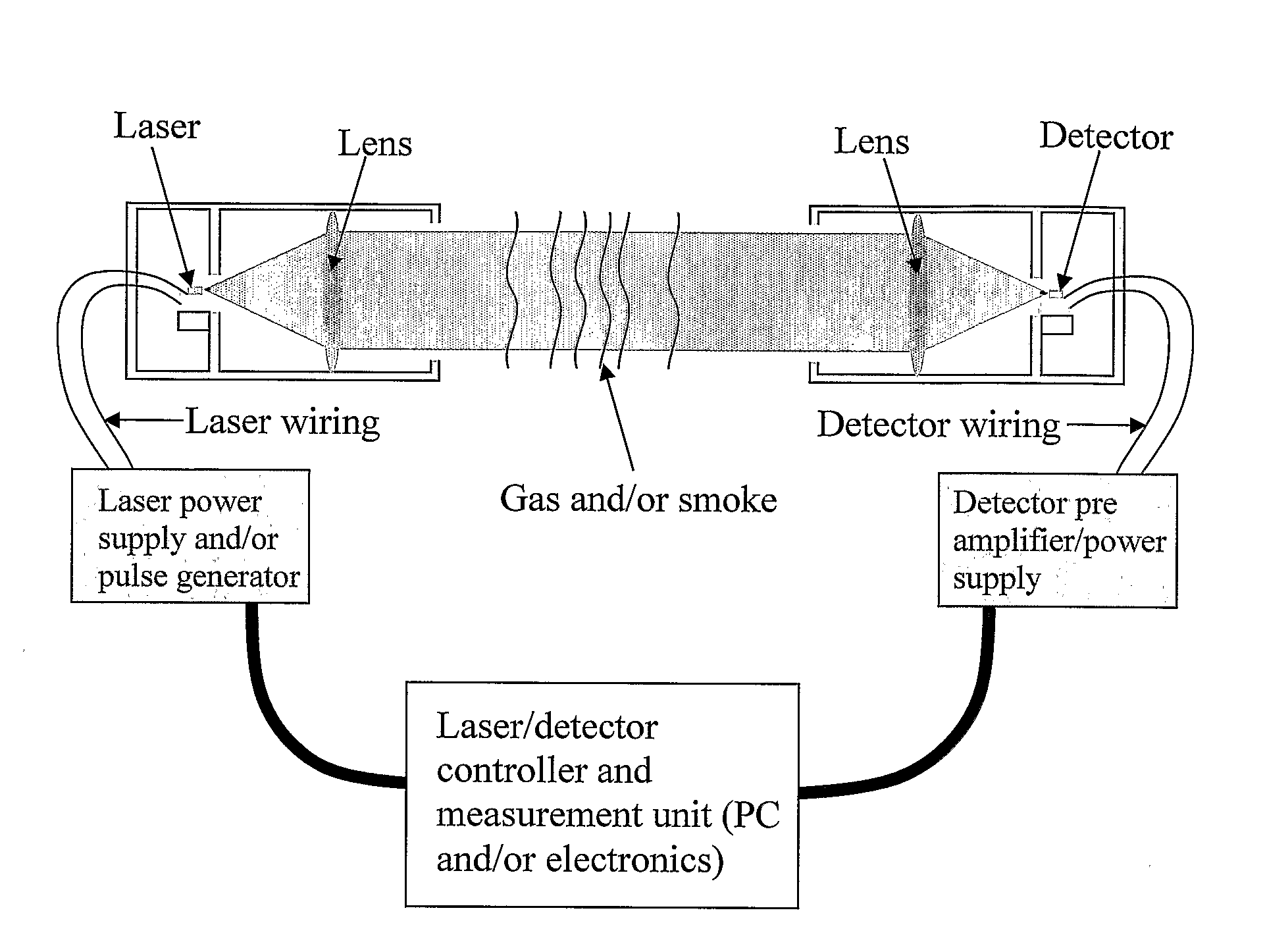
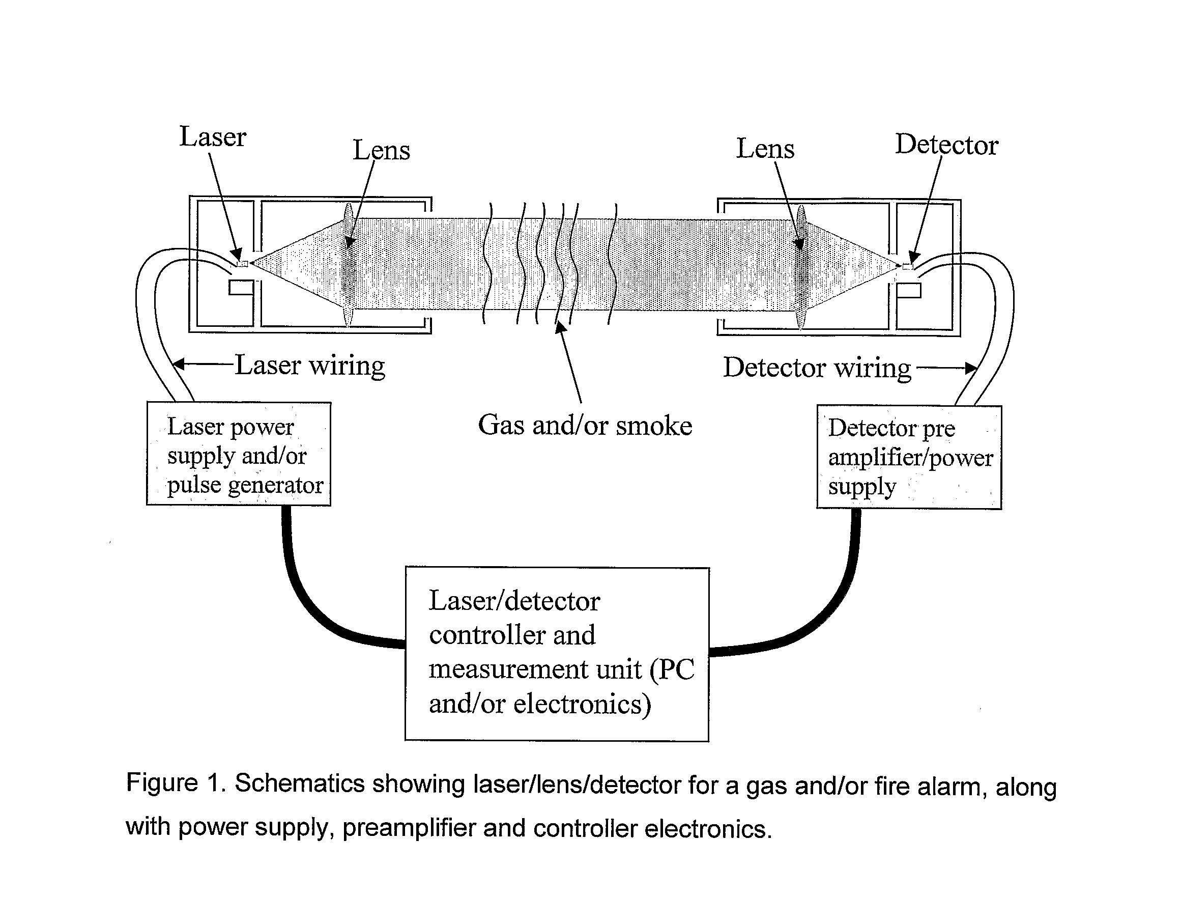
[0055]A system was built on the basis of a FPCM-2301 Mid-IR Fabry Perot laser at ˜2.3 μm (from Intopto A / S, Norway) which was mounted into a “transmitter”-housing with a collimating lens and power supply as shown in FIG. 1. The power supply of the tested system was actually mounted on the backside of the housing (unlike in the figure which has a separate box), so that the distance between the power supply and the laser was less. In front of the laser, we mounted a Concave-flat lens which had the laser in its focal point so that the laser beam was collimated into a parallel beam. This made it easy to adjust distance between the transmitter (containing the laser) and the detector. As shown in FIG. 1, the detector was mounted in a “reciever”-housing with a flat-Concave lens so that most of the laser beam was focused onto the detector. The pin-detector in the housing (a 2.3 μm InGaAs pin-detector from Sensors Unlimited Ltd., USA) was connected to a preamplifier which was mounted on the ...


PUM


Abstract

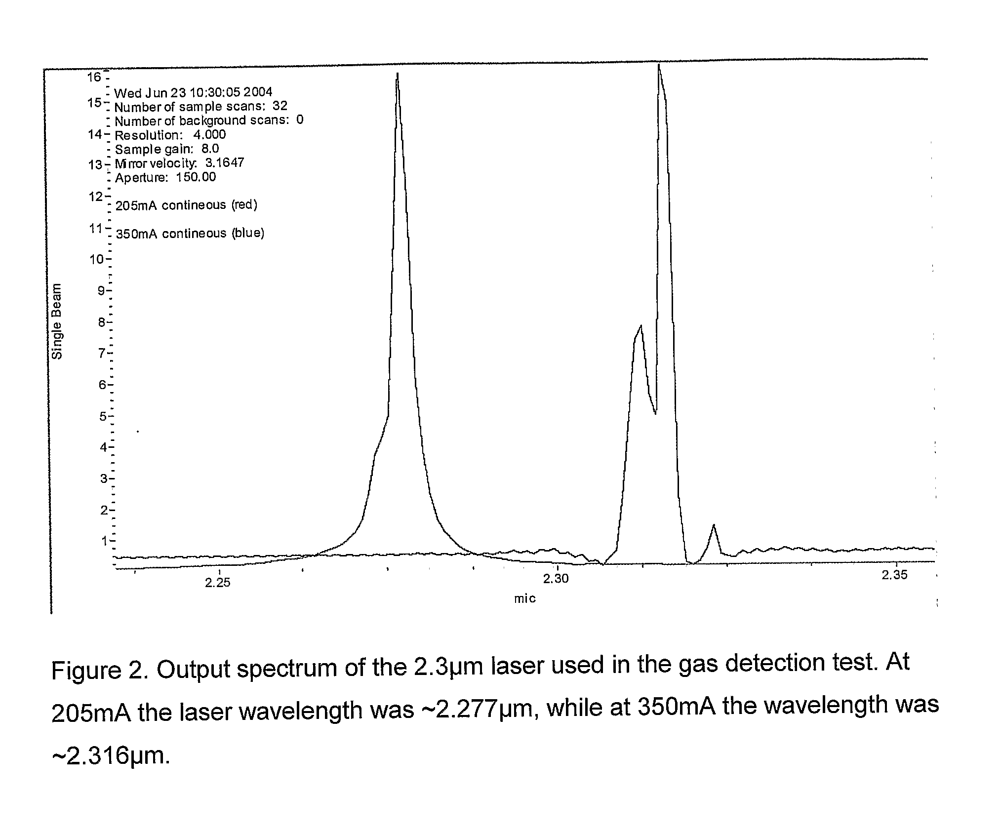
The subject invention relates to a new alarm which is based on using a quarternary tunable Mid-IR laser to measure both particles and gas at the same time. The measurement is done within an area of which the gas of interest will absorb the Mid-IR radiation. By widely tuning the emission wavelength of the laser, several wavelengths can be measured in order to accurately find both gas composition and particle density with one laser based sensor. We tested a new device which use radiation between 2.27 μm and 2.316 μm. Methane gas reduces intensity of the radiation at certain wavelengths in this device, while particles / fog reduce intensity for all wavelengths. In this case, fog should not trigger an alarm, while methane leaks should. This can also be applied for CO and smoke in which one sensor will measure both parameters to sound an alarm instead of just one parameter.

Description

FIELD OF THE INVENTION[0001]The present invention relates to the use of a tunable Infrared Fabry Perot, Ψ-junction laser or alike to detect CO2, CO, NH3, NOx, SO2, CH4, Hydrocarbon gas / fluids or alike and / or smoke / particles, to the use of laser radiation around the 1.0-10.0 μm wavelength area to detect CO2, CO, NH3, NOx, SO2, CH4, Hydrocarbon gas / fluids or alike and / or smoke / particles, to the use of AlGaAs / InGaAs-, AlGaAsP / InGaAsP-, AlGaAsP / InGaAsN-, AlGaAsSb / InGaAsSb- or AlInGaAsSb / InGaAsSb-laser or alike to detect CO2, CO, NH3 NOx, SO2, CH4, Hydrocarbon gas / fluids or alike and / or smoke / particles and to the use of a laser and p-i-n detector or alike with response around the 1.0-10.0 μm wavelength area to measure and detect CO2, CO, NH3, NOx, SO2, CH4, Hydrocarbon gas / fluids or alike and / or smoke / particles.[0002]The invention also relates to using such gas and / or fluid and / or smoke / particle detection devices in one or two units for detection of gas leak, gas anomality, fluid anomali...

Claims


Application Information

Patent Timeline
IPC IPC(8): G08B17/103G01N21/00G01N21/35G01N21/39G01N21/53G08B
CPCG01N21/3504G01N21/39G01N21/53G01N21/532G08B17/103G01N2021/392G01N2021/399G01N2201/0612G01N2021/1793G01N21/85G08B17/113
Inventor BUGGE, RENATO
Owner INTEGRATED OPTOELECTRONICS
Learn More