Systems and methods for insitu lens cleaning in immersion lithography

Inactive Publication Date: 2008-08-21
ASML HLDG NV
View PDF103 Cites 5 Cited by
  • Summary
  • Abstract
  • Description
  • Claims
  • Application Information

AI Technical Summary

Benefits of technology

[0010]The invention provides an efficient system and method for insitu cleaning of final lens element that does not damage the final lens element, nor does it require the painstaking task of lens removal and repositioning.

Problems solved by technology

This approach to lens cleaning is time consuming, as the lens must typically be removed.
Moreover, the approach is not well suited for new immersion lithography exposure systems.
The high refractive index immersion fluids are organic and breakdown under ultraviolet exposure to produce carbonaceous deposits, which are not easily manually cleaned from the surface of lens.

Method used


Image

  • Systems and methods for insitu lens cleaning in immersion lithography
  • Systems and methods for insitu lens cleaning in immersion lithography
  • Systems and methods for insitu lens cleaning in immersion lithography

Examples


Embodiment Construction

[0017]While the present invention is described herein with reference to illustrative embodiments for particular applications, it should be understood that the invention is not limited thereto. Those skilled in the art with access to the teachings provided herein will recognize additional modifications, applications, and embodiments within the scope thereof and additional fields in which the present invention would be of significant utility.

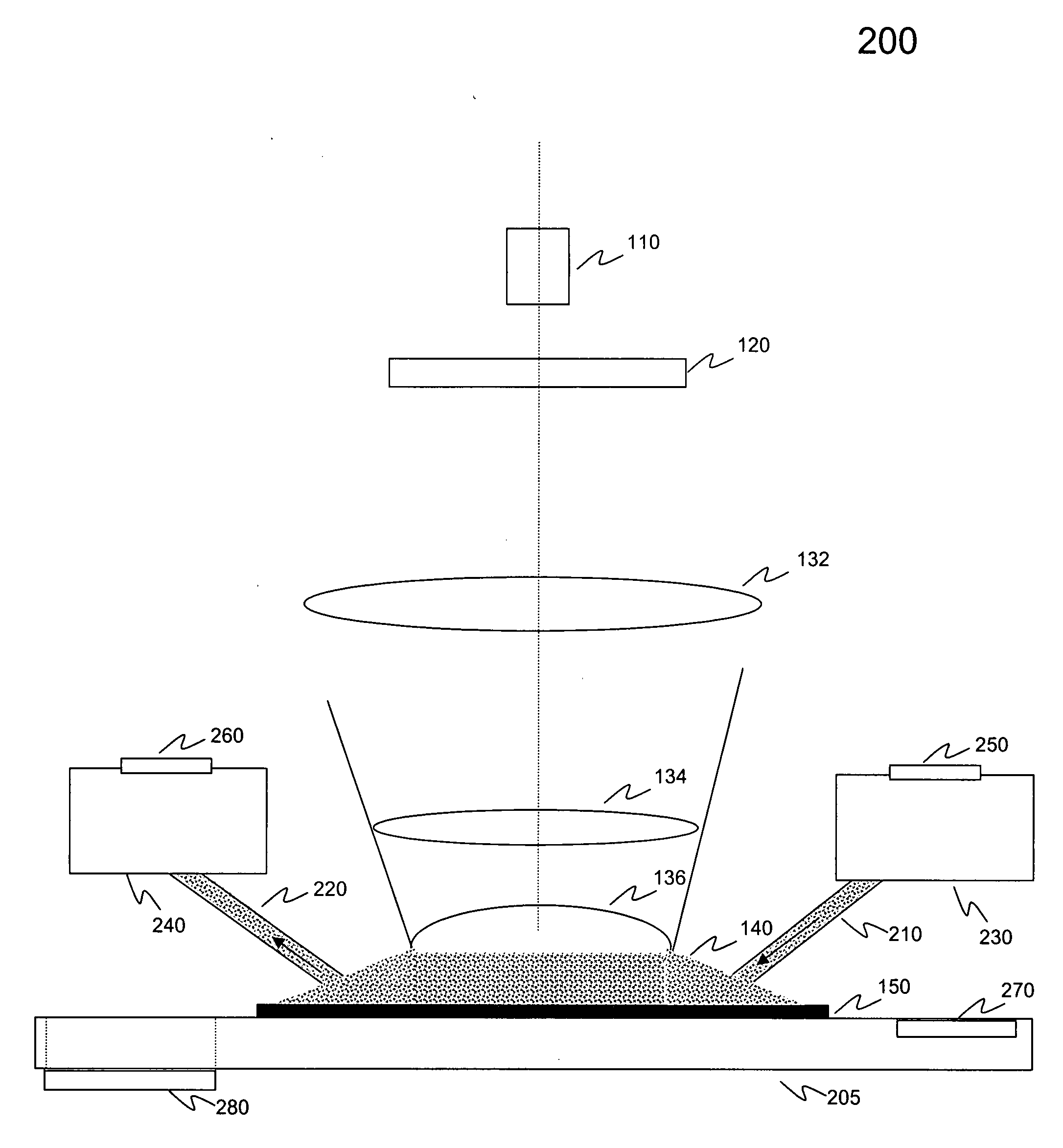
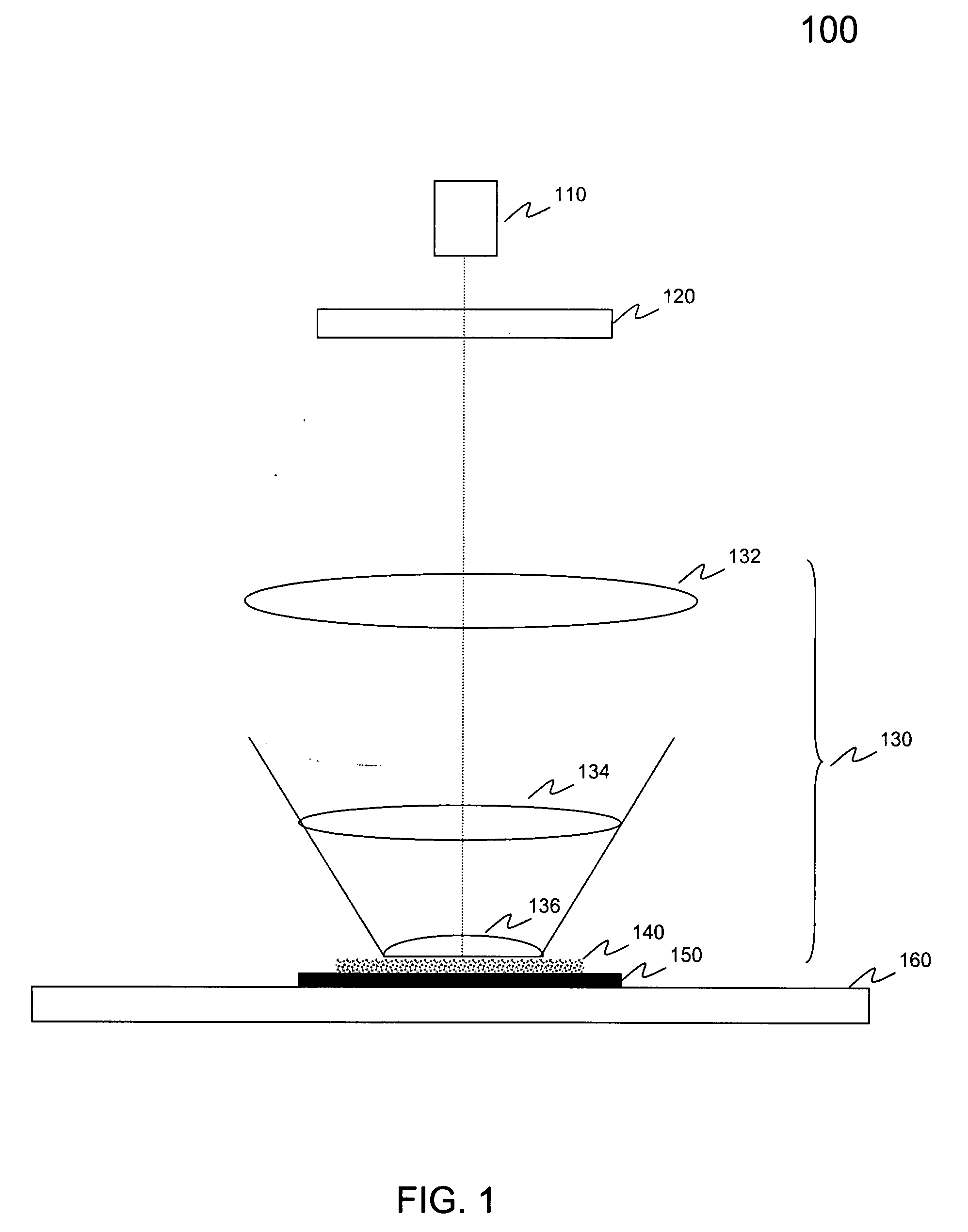
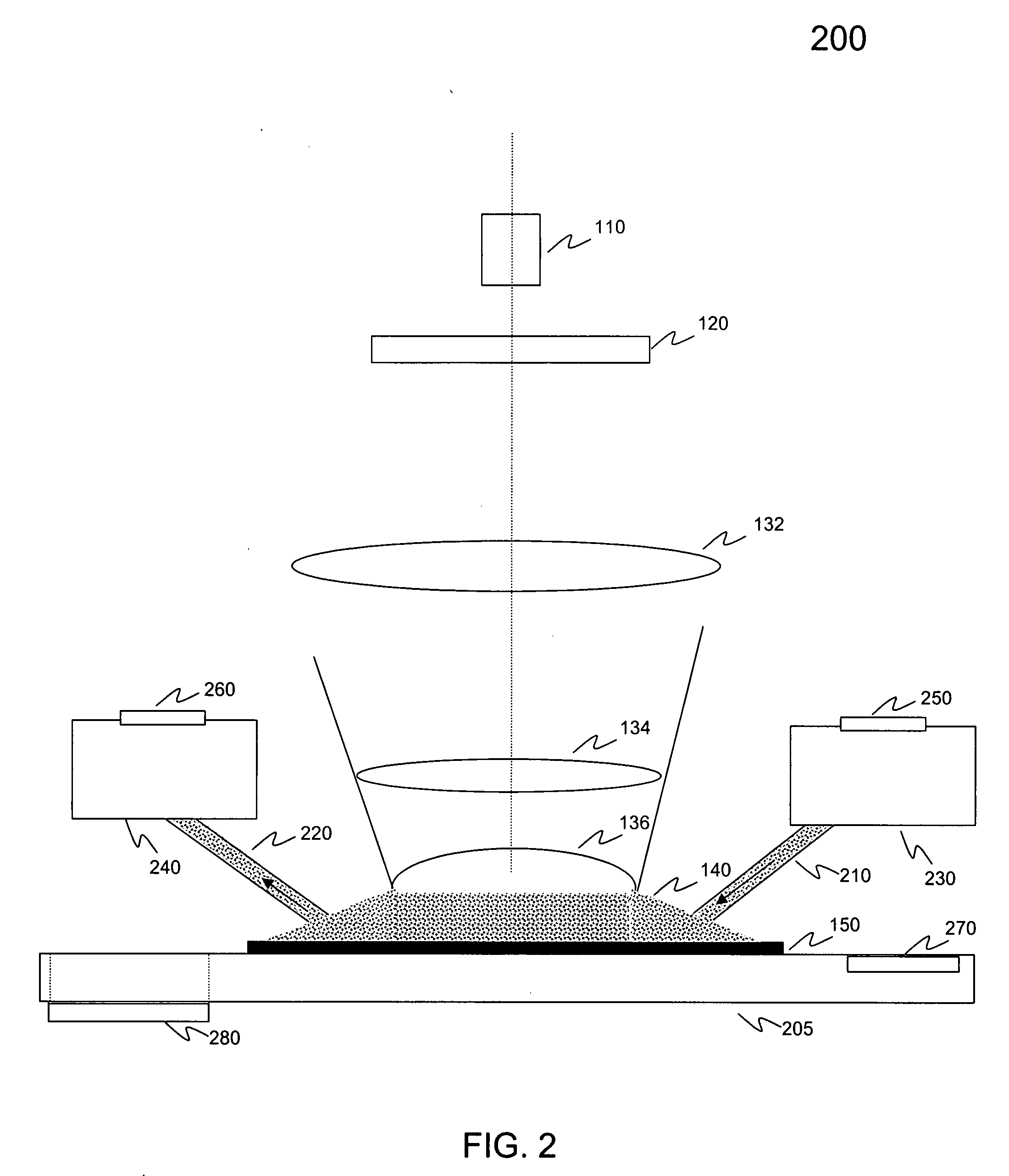
[0018]In immersion lithography systems, liquid is injected into the space between a projection optical system exit window and a substrate surface that is being worked. FIG. 1 is a block diagram of immersion lithography system 100. System 100 includes energy source 110, pattern generator 120, and projection optical system 130. Energy source 110 produces exposure doses of energy that are used to pattern a substrate, such as substrate 150, that is being worked. Pattern generator 120 generates the pattern to be produced on substrate 150.

[0019]Projecti...


PUM


Abstract

An immersion lithography apparatus is provided that includes an energy source, a projection optical system, a stage, a showerhead including an immersion liquid supply device and an immersion liquid discharge device that produces a flow of liquid within an exposure zone, and a cleaning device that cleans a portion of the projection optical system having been contacted with the immersion liquid by means of a cleaning gas. In an embodiment, the cleaning device includes a gas supply device and a gas discharge device that produce a flow of cleaning gas into the exposure zone. In embodiments, the apparatus includes a stage that includes a dose sensor and / or an ultra-violet light source. A method for insitu cleaning of a final lens element within an immersion lithography system having an immersion fluid showerhead that provides immersion fluid to an exposure zone of the immersion lithography system is also provided.

Description

BACKGROUND[0001]1. Field of the Invention[0002]The present invention relates to immersion lithography, more particularly, to providing methods for insitu lens cleaning in immersion lithography systems.[0003]2. Related Art[0004]Lithography is a process used to create features on the surface of substrates. Such substrates can include those used in the manufacture of flat panel displays (e.g., liquid crystal displays), semiconductor wafers, circuit boards, various integrated circuits, print heads, macro / nano-fluidic substrates, and the like. During lithography, a substrate, which is disposed on a substrate stage, is exposed to an image projected onto the surface of the substrate by exposure optics located within a lithography apparatus.[0005]The projected image produces changes in the characteristics of a layer, for example, photoresist, deposited on the surface of the substrate. These changes correspond to the features projected onto the substrate during exposure. Subsequent to exposu...

Claims


Application Information

Patent Timeline
IPC IPC(8): G03B27/42
CPCG03F7/70925G03F7/70341G03F7/20
Inventor SEWELL, HARRYMARKOYA, LOUIS JOHN
Owner ASML HLDG NV
Why Eureka
Try Eureka