Power Converter
a power converter and converter technology, applied in the direction of cooling/ventilation/heating modification, electrical equipment, semiconductor devices, etc., can solve the problems of inability to achieve the miniaturization of the power converter, inability to refine the productivity, and low flexibility in cooling the electronic parts, so as to improve the flexibility of cooling the electronic parts and improve productivity
- Summary
- Abstract
- Description
- Claims
- Application Information
AI Technical Summary
Benefits of technology
Problems solved by technology
Method used
Image
Examples
first embodiment
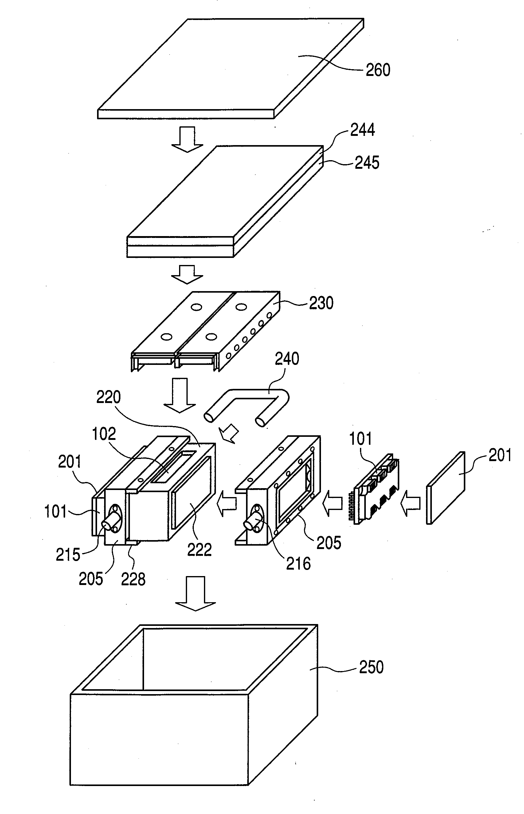
[0064]FIG. 3 illustrates an exploded schematic diagram of the power converter of a first embodiment. FIG. 4 illustrates a cross-sectional view of the power converter of the first embodiment as seen from above.
[0065]The configuration of the power converter 100 in this embodiment will now be described.
[0066]The gate substrate 201 is provided with a drive circuit for controlling the drive of a switching device such as an IGBT and a MOSFET.
[0067]The power semiconductor module 101 includes a plurality of switching devices that are on / off controlled based on a control signal from the gate substrate 201. With such control, a DC voltage applied between the switching device of the upper arm and the switching device of the lower arm is converted to AC voltage of three phases; U-phase, V-phase, and W-phase.
[0068]A cooling jacket 205 includes a flow path of a coolant, such as water, for cooling the switching device that generates a lot of heat. One of the two cooling jackets 205 is provided wit...
second embodiment
[0088]FIG. 6 illustrates an exploded schematic view of the power converter of a second embodiment.
[0089]As the basic configuration of this embodiment is identical to that of the first embodiment, descriptions of like elements will be omitted.
[0090]A power converter of this embodiment is provided with a DC-DC converter 270 in addition to the constituent elements included in the power converter of the first embodiment. The DC-DC converter 270 is designed to increase or decrease a predetermined DC voltage. As shown in FIG. 6, the connector 240 passes through the DC-DC converter 270, allowing effective cooling of heat generated by the DC-DC converter 270.
[0091]Because the DC-DC converter 270 also generates heat, when mounting the DC-DC converter 270 in the power converter 100, the heat radiation efficiency of the DC-DC converter 270 can be improved by bringing the DC-DC converter 270 into contact with the connector 240.
[0092]FIG. 7 illustrates an enlarged schematic diagram of the DC-DC ...
third embodiment
[0095]FIG. 9 illustrates an exploded schematic diagram of the power converter of a third embodiment.
[0096]As the basic configuration of this embodiment is identical to that of the first embodiment, descriptions of like elements will be omitted.
[0097]The power converter 100 of this embodiment includes a strut structure 280. The strut structure 280 is provided with two metal plates, which are fixed at a center portion 282. With the center portion as a reference point, the gap between the two metal plates can be altered.
[0098]In this embodiment, the strut structure 280 used as reinforcement is connected to the two cooling jackets 205. The use of such a strut structure 280 can realize strong fixation of each constituent element and thus improves resistance to vibration.
[0099]An assembly method of the power converter 100 of this embodiment is the same as that of the first embodiment up to the assembling of the gate substrate 201, power semiconductor module 101, cooling jackets 205, DC bu...
PUM
 Abstract
Description
Claims
Application Information
 - R&D
- Intellectual Property
- Life Sciences
- Materials
- Tech Scout
- Unparalleled Data Quality
- Higher Quality Content
- 60% Fewer Hallucinations
Browse by: Latest US Patents, China's latest patents, Technical Efficacy Thesaurus, Application Domain, Technology Topic, Popular Technical Reports.
© 2025 PatSnap. All rights reserved.Legal|Privacy policy|Modern Slavery Act Transparency Statement|Sitemap|About US| Contact US: help@patsnap.com


