Direct Smelting Plant

Inactive Publication Date: 2008-08-28
TECH RESOURCES PTY LTD
View PDF12 Cites 11 Cited by
  • Summary
  • Abstract
  • Description
  • Claims
  • Application Information

AI Technical Summary

Problems solved by technology

Building a direct smelting plant of the kind described above presents major problems in that it is necessary to erect various kinds of major equipment sourced from different manufacturers at a single site area.

Method used


Image

  • Direct Smelting Plant
  • Direct Smelting Plant
  • Direct Smelting Plant

Examples


Embodiment Construction

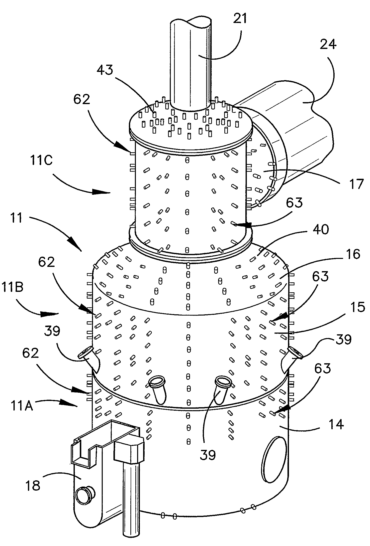
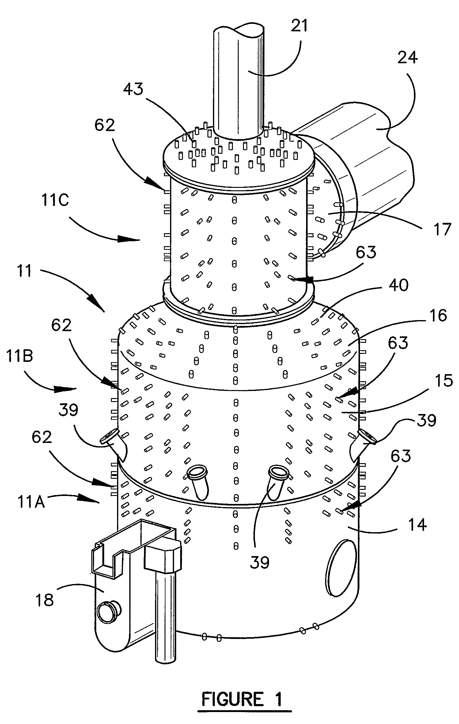
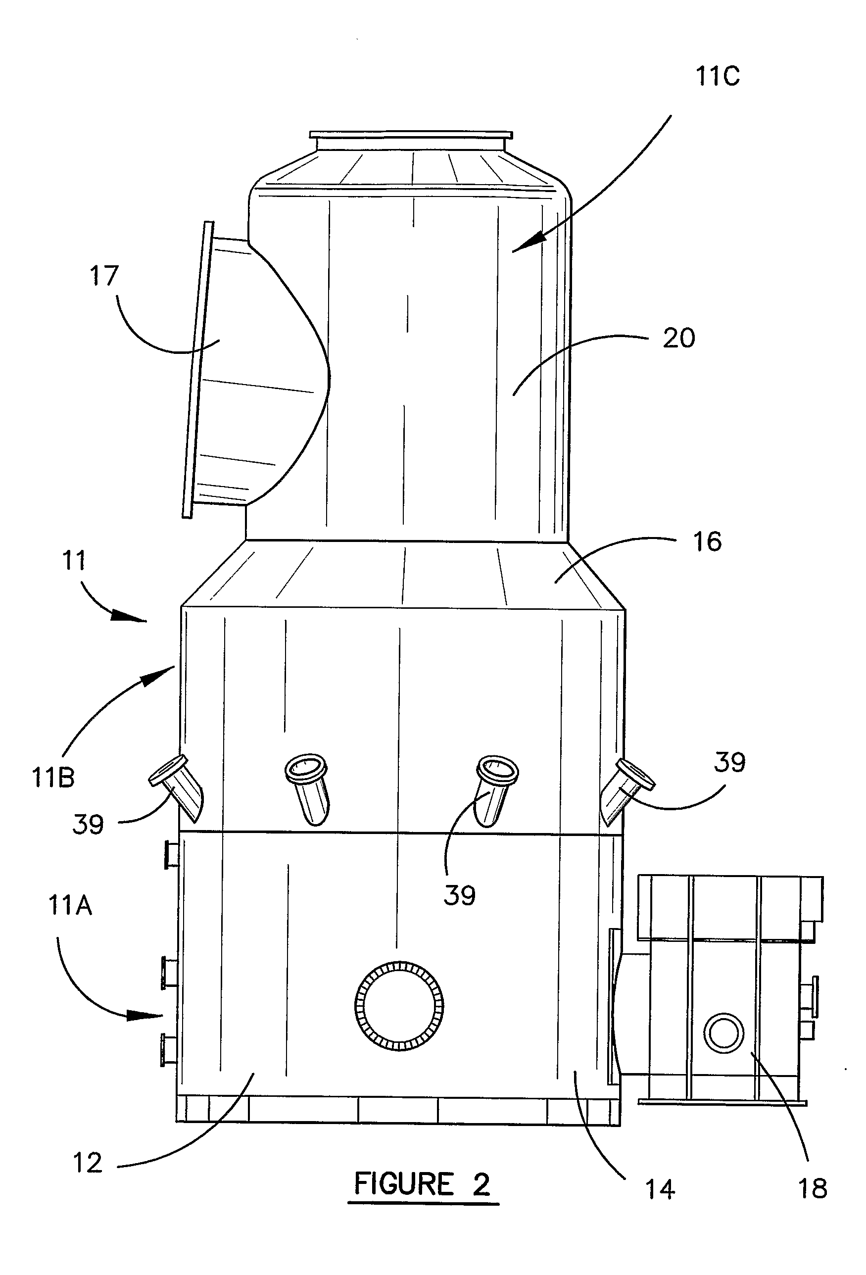
[0049]The drawings show a direct smelting vessel 11 suitable for operation by the HIsmelt process as described in International Patent Publication WO 96 / 31627. Vessel 11 has a hearth 12 that is lined with refractory bricks; side walls 14 which form a generally cylindrical barrel extending upwardly from the hearth; an upper barrel section 15 and a roof 16 leading to an offgas chamber 20 with an outlet 17 for offgases; a forehearth 18 for discharging molten metal continuously; and a tap hole for discharging molten slag.

[0050]Vessel 11 is designed to be fitted with a downwardly extending gas injection lance 21 for delivering a hot air blast into the upper region of the vessel and eight solids injection lances (not shown) extending downwardly and inwardly through the side walls for injecting iron ore, solid carbonaceous material and fluxes entrained in an oxygen deficient carrier gas into the bottom part of the vessel.

[0051]Gas injection lance 21 receives an oxygen enriched hot air flow...


PUM

PropertyMeasurementUnit
angleaaaaaaaaaa
U-shape,aaaaaaaaaa
U-shapeaaaaaaaaaa

Abstract

Method of constructing and installing a direct smelting unit comprising a smelting vessel (11). The vessel is prefabricated off site in three modules (11A, 11B, 11C) which are then transported to the installation site where they are hoisted by a crane and deposited sequentially on top of one another and joined together by welding to form a unitary vessel. The vessel modules are prefabricated so as to be internally lined with water cooling panels connected to water inlet and outlet connectors (62) on the exterior of the circumferential wall sections of those modules. A vessel access tower is formed in modules brought together to envelop the tower and carrying water supply and return piping which is connected to the water inlet and outlet connectors (62) of the cooling panels.

Description

TECHNICAL FIELD[0001]The present invention relates to direct smelting plant for producing molten metal in pure or alloy form from a metalliferous feed material such as ores, partly reduced ores and metal-containing waste streams.[0002]A known direct smelting process, which relies principally on a molten metal layer as a reaction medium, and is generally referred to as the HIsmelt process, is described in International Patent Publication WO 96 / 31627 (International Patent Application PCT / AU96 / 00197) in the name of the applicant. The HIsmelt process as described in the International application comprises:[0003](a) forming a bath of molten iron and slag in a vessel;[0004](b) injecting into the bath:[0005](i) a metalliferous feed material, typically metal oxides; and[0006](ii) a solid carbonaceous material, typically coal, which acts as a reductant of the metal oxides and a source of energy; and[0007](c) smelting metalliferous feed material to metal in the metal layer.[0008]The term “sme...

Claims


Application Information

Patent Timeline
Patent Type & Authority Applications(United States)
IPC IPC(8): E04H5/02E04G21/14E04H12/00E04F17/04C21B11/00C21B13/00C21C5/56F27B1/10F27B1/16F27B1/21F27B1/24F27B3/10F27B3/19F27B3/20F27B3/24F27D3/14F27D3/15F27D99/00
CPCC21B11/00C21B13/0006C21C5/56F27B1/16F27B1/21F27D3/159F27B3/19F27B3/20F27B3/24F27D3/14F27D3/1509F27B1/24C21B2100/64Y02P10/134F27B1/10
Inventor IONS, PHILIP JAMESHAYTON, MARK
Owner TECH RESOURCES PTY LTD
Why Eureka
Try Eureka