Cleaning member, cleaning method, and device manufacturing method

a technology of cleaning member and cleaning method, which is applied in the field of cleaning member, can solve the problems of substrate holding member being polluted by infiltrating liquid, unable to properly hold substrate, and substrate it holds becoming polluted

Inactive Publication Date: 2008-08-28
NIKON CORP
View PDF63 Cites 26 Cited by
  • Summary
  • Abstract
  • Description
  • Claims
  • Application Information

AI Technical Summary

Benefits of technology

[0015]According to the fourth aspect of the invention, by holding the substrate with a properly cleaned substrate-holding member and exposing the substrate to light, it is possible to manufacture a device having a desired performance.

Problems solved by technology

In an immersion exposure apparatus, when liquid infiltrates into places such as a gap between a substrate and a substrate-holding member, there is a possibility that part of the substrate-holding member be polluted by the infiltrating liquid, or by foreign bodies and impurities that have become mixed in the liquid.
If the substrate-holding member is left in this polluted state, there are possibilities that it will become unable to properly hold the substrate, that the substrate it holds will become polluted, and that pollution will spread.
Such problems can make it impossible to properly expose the substrate.

Method used


Image

  • Cleaning member, cleaning method, and device manufacturing method
  • Cleaning member, cleaning method, and device manufacturing method
  • Cleaning member, cleaning method, and device manufacturing method

Examples


first embodiment

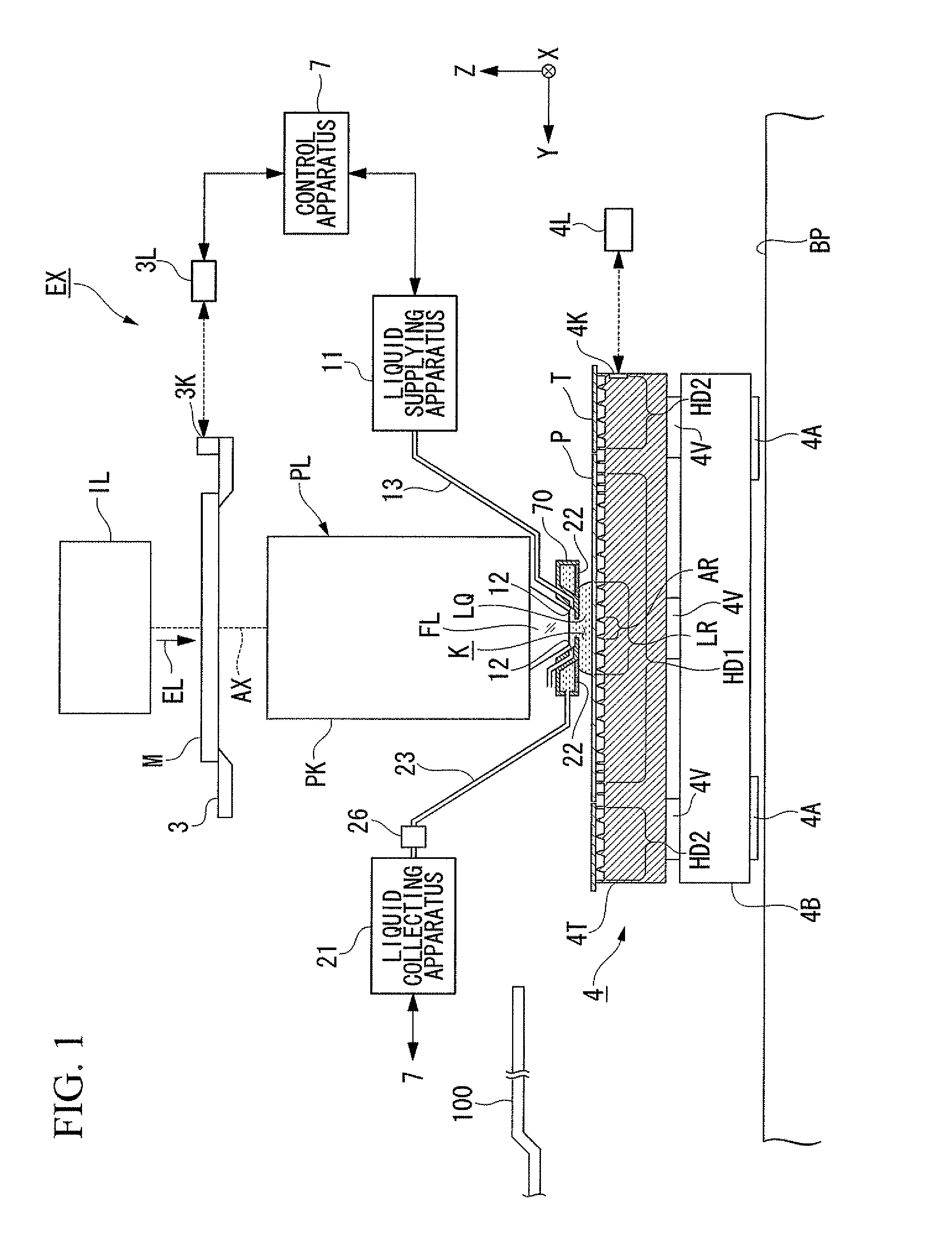
[0034]A first embodiment will be explained. FIG. 1 is a view of a general configuration of an exposure apparatus EX according to a first embodiment. In FIG. 1, the exposure apparatus EX includes a movable mask stage 3 that holds a mask M, a movable substrate stage 4 that holds a substrate P for exposure, an illumination system IL that illuminates the mask M with exposure light EL, a projection optical system PL that projects an image of a pattern of the mask M illuminated by the exposure light EL onto the substrate P, a conveying device 100 that can convey the substrate P with respect to the substrate stage 4, and a control apparatus 7 that controls the overall exposure apparatus EX.

[0035]The substrate P for exposure here is used in manufacturing a device and includes, for example, a substrate made by applying a photosensitive material (photo resist) to a base material as in the case of a semiconductor wafer such as a silicon wafer, or a substrate to which, in addition to a photosen...

second embodiment

[0125]Subsequently, a second embodiment will be explained. In this embodiment, constituent parts which are the same or similar to those of the embodiment described above are represented by same reference codes and are not repetitiously explained.

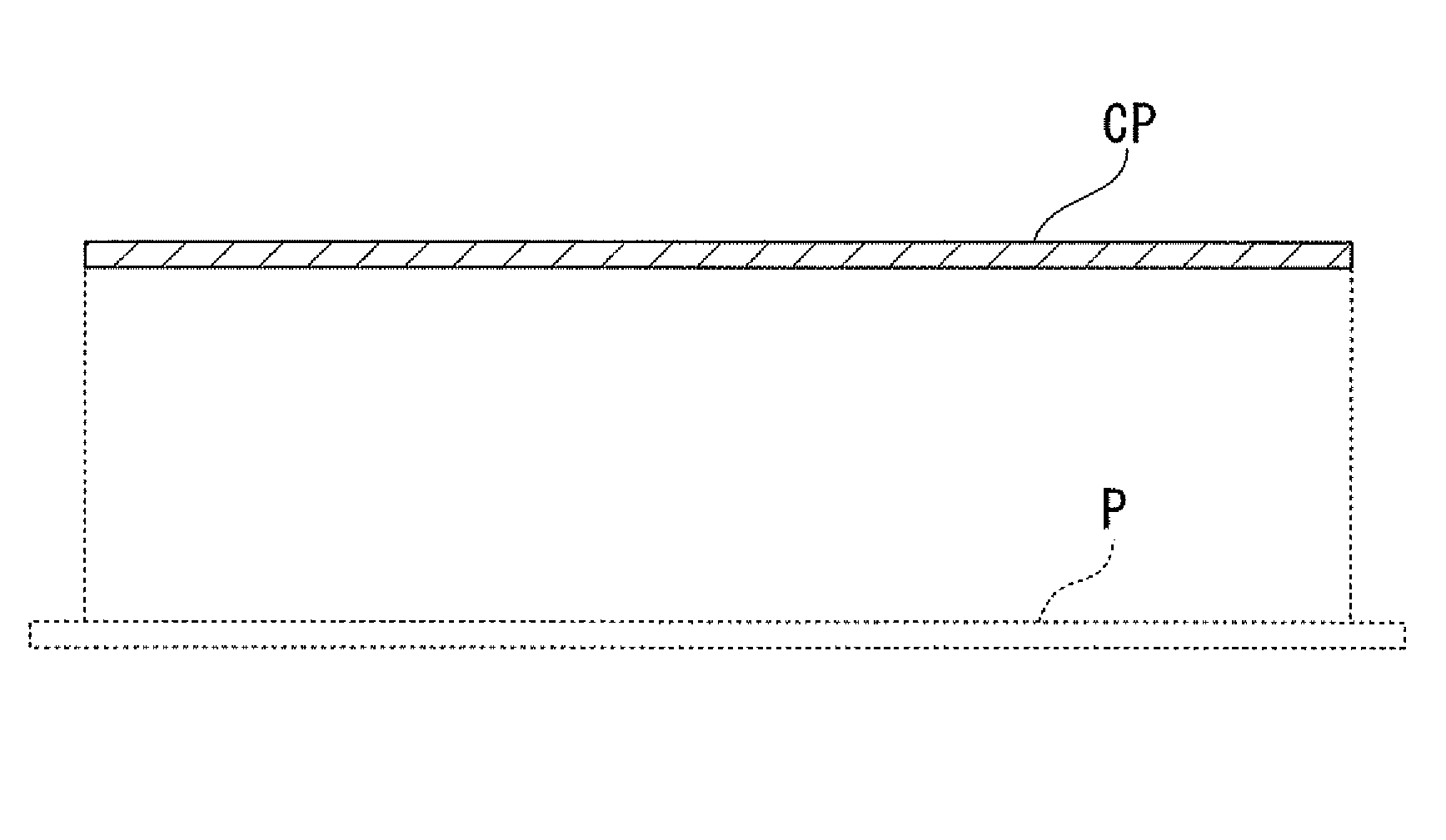
[0126]While in the first embodiment, as shown schematically in FIG. 12A, the substrate CP has an outer diameter that is smaller than the diameter of the outer rim of the first top face 33A of the first peripheral wall 33 and larger than the diameter of the inner rim of the first top face 33A of the first peripheral wall 33, as shown in FIG. 12B, it can have an outer diameter that is larger than the outer rim of the first top face 33A of the first peripheral wall 33. In this case, although the first top face 33A of the first peripheral wall 33 is not opened, since an eighth gap G8′ between the substrate CP and the plate member T is larger than the fifth gap G5 between the substrate P and the plate member T, the liquid LQ for cleaning can be s...

third embodiment

[0129]Subsequently, a third embodiment will be explained. FIG. 14 is a view of the vicinity of a nozzle member 70 according to a third embodiment. In this embodiment, the nozzle member 70 includes a liquid ejection hole 90 capable of ejecting liquid LQ in the immersion space LR, the liquid LQ being ejected from the liquid spray hole 90 in the immersion space LR, thereby forming a rapid flow of liquid LQ in the immersion space LR. The rapid flow of liquid LQ acts upon the surface of the table 4T. This assists the removal of polluting substances that stick to the surface of the table 4T.

[0130]In the first to third embodiments, the cleaning operation using the substrate CP can, for example, be executed each time a predetermined number of substrates P are processed, for each lot, at predetermined time intervals, etc.

[0131]As described above, the exposure apparatus EX includes the detecting device 26 that can detect the quality (water quality) of the liquid LQ for exposure collected from...


PUM

PropertyMeasurementUnit
wavelengthaaaaaaaaaa

Abstract

A cleaning member is smaller than a substrate for exposure where exposure light is irradiated, and at least part of a substrate-holding member that holds a rear face of the substrate for exposure is held by the substrate-holding member in order to clean.

Description

CROSS-REFERENCE TO RELATED APPLICATION[0001]The present application claims priority on Japanese Patent Application No. 2006-244271, filed Sep. 8, 2006, the content of which is incorporated herein by reference.BACKGROUND[0002]1. Field of the Invention[0003]The present invention relates to a cleaning member for cleaning a substrate-holding member that holds a substrate, a cleaning method, and a device manufacturing method.[0004]2. Related Art[0005]As an exposure apparatus used in a photolithography process, an immersion exposure apparatus that exposes a substrate via liquid is conventionally known, and is disclosed, for example, in PCT International Publication No. WO 99 / 49504 and Japanese Patent Application, Publication No. 2004-289127.[0006]In an immersion exposure apparatus, when liquid infiltrates into places such as a gap between a substrate and a substrate-holding member, there is a possibility that part of the substrate-holding member be polluted by the infiltrating liquid, or ...

Claims


Application Information

Patent Timeline
Patent Type & Authority Applications(United States)
IPC IPC(8): B08B3/04B08B13/00B08B7/00B08B1/00
CPCG03F7/70341G03F7/70716Y10T29/49H01L21/68735H01L21/6875H01L21/67051G03F7/70908
Inventor SHIBAZAKI, YUICHI
Owner NIKON CORP
Why Eureka
Try Eureka