Phase Plate For Phase-Contrast Electron Microscope, Method For Manufacturing the Same and Phase-Contrast Electron Microscope

a technology of electron microscope and phase plate, which is applied in the direction of vacuum evaporation coating, coating, plasma technique, etc., can solve the problems of unnecessary lens effect to distort images, not yet successful, and none of the methods proposed so far could not completely prevent charging in the phase plate of the phase-contrast electron microscop

Inactive Publication Date: 2008-08-28
NAGAYAMA IP HLDG
View PDF4 Cites 22 Cited by
  • Summary
  • Abstract
  • Description
  • Claims
  • Application Information

AI Technical Summary

Benefits of technology

[0017]According to the present invention, the lens effect incident to the charging of the phase plate for use in a phase-contrast electron microscope can be prevented completely, making it possible to apply various types of phase-contrast electron microscopes such as by a Zernike phase contrast method, a differential contrast method, and the like to an extensive field of material science such as metallurgy, semiconductor industries and ceramic industries.

Problems solved by technology

In a case of using a conductive material for the phase plate in the phase-contrast electron microscope, it has been known long since that charging of the phase plate is not caused by the phase plate itself but caused by foreign insulation contamination intruded in the course of manufacturing the phase plate.
While efforts have been made in various studies for eliminating non-volatile insulation contaminations to prepare a completely clean phase plate, they have not yet been successful.
Even aluminum considered as a conductive thin film material of excellent antistatic effect can not get out of charging as a problem in the phase-contrast electron microscope.
Such charging induced in the oxide film by electron irradiation bends the trajectory of electron beams, and results in an unnecessary lens effect to distort images.
The essence of the problem resides in that the space potential induced by static charges forms a sort of a lens to disturb the intrinsic performance of the phase plate.
As described above, none of the methods proposed so far could not completely prevent charging in the phase plate of the phase-contrast electron microscope.

Method used


Image

  • Phase Plate For Phase-Contrast Electron Microscope, Method For Manufacturing the Same and Phase-Contrast Electron Microscope
  • Phase Plate For Phase-Contrast Electron Microscope, Method For Manufacturing the Same and Phase-Contrast Electron Microscope
  • Phase Plate For Phase-Contrast Electron Microscope, Method For Manufacturing the Same and Phase-Contrast Electron Microscope

Examples


Embodiment Construction

[0024]The present invention has the feature as described above and the embodiment thereof will be described.

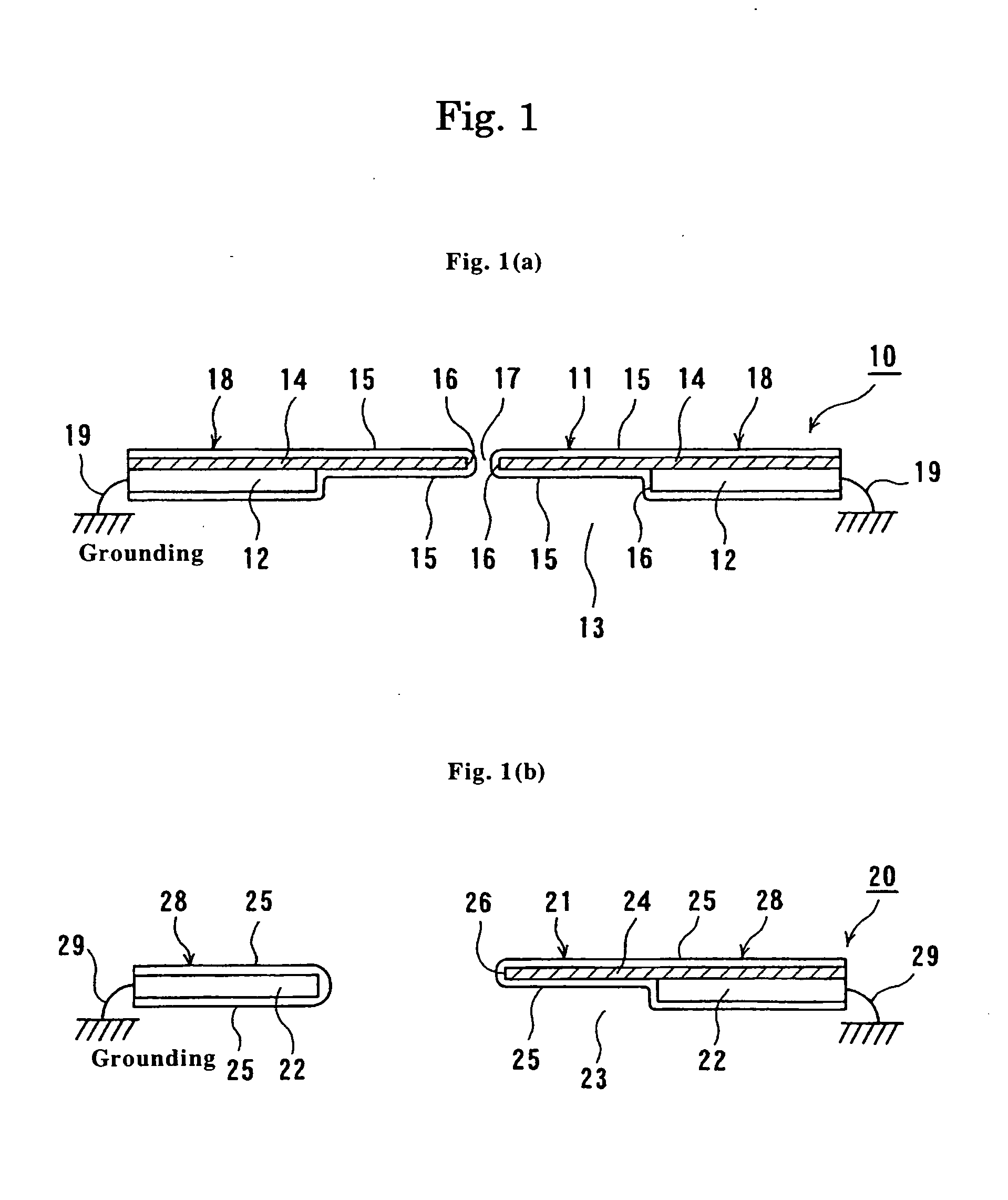
[0025]FIGS. 1(a) and (b) are, respectively, cross sectional views schematically showing embodiments of a phase plate for use in a phase-contrast electron microscope according to the present invention.

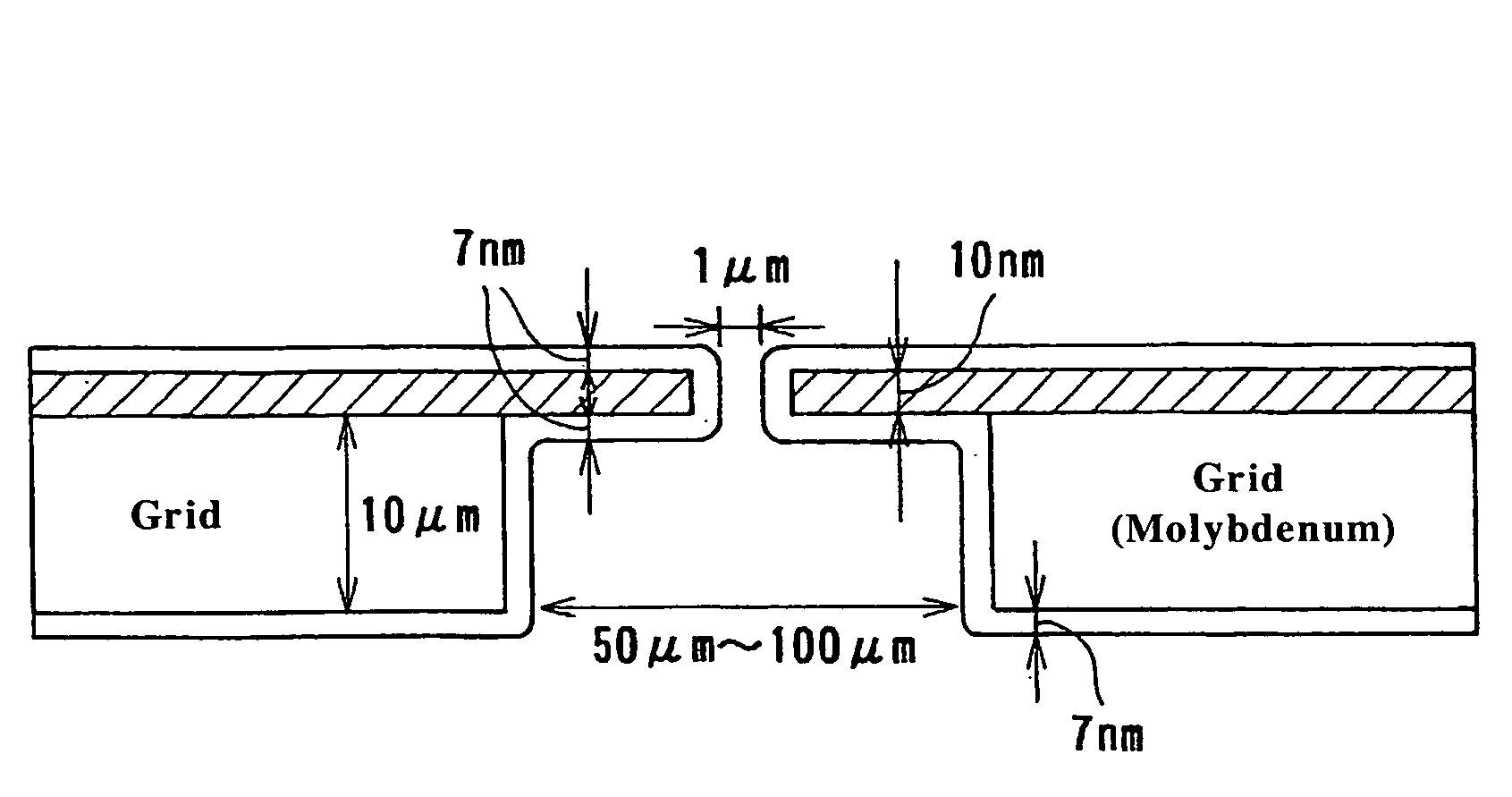
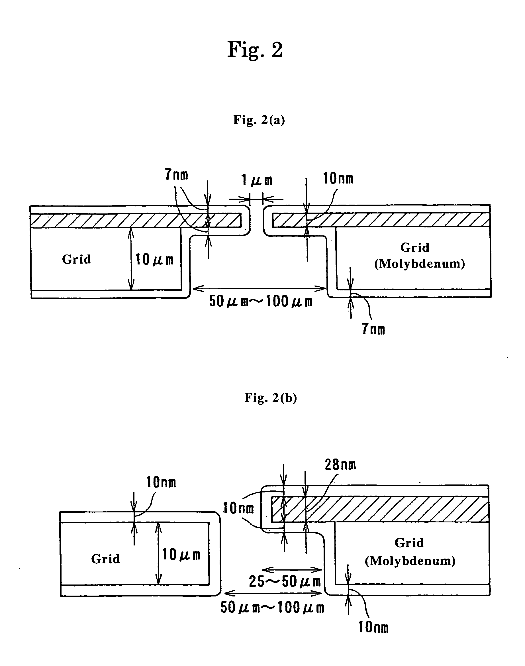
[0026]At first, referring to a phase plate (10) shown in FIG. 1(a), the phase plate (10) is referred to as a Zernike phase plate, has a phase plate body (11) and a grid (12) as a phase plate support, and is disposed to the path of electrons having passed through an objective lens of a phase-contrast electron microscope. The phase plate (10) is adapted to shift the phase of electrons by π / 2. The phase plate body (11) comprises a conductive core phase plate (14) supported on the grid (12) having a circular opening (13) and a conductive shielding thin film (15) disposed on both surfaces thereof. A regular circle through hole is formed in the center of the core phase plate (14), a con...


PUM

PropertyMeasurementUnit
sizeaaaaaaaaaa
sizeaaaaaaaaaa
thicknessaaaaaaaaaa

Abstract

A phase plate (10) for phase-contrast electron microscopes is characterized by comprising a conductive core phase plate (14) which has a phase plate body (11) and a phase plate support (12) supporting it and is arranged in the path of electrons having passed through the objective lens of an electron microscope and in which the phase plate body (11) is so supported on the phase plate support (12) having an opening (13) as to cover at least a part of the opening (13) and a conductive shield thin film (15) covering the periphery of the core phase plate (14) including the upper and lower sides thereof. Consequently, a phase plane for phase-contrast electron microscopes preventing the lens effect incident to charging completely and applicable to the field of material science, its manufacturing method and a phase-contrast electron microscope can be provided.

Description

TECHNICAL FIELD[0001]The present invention concerns a phase plate for use in a phase-contrast electron microscope, a method for manufacturing the same, and a phase-contrast electron microscope. More specifically, the present invention concerns a phase plate for use in a phase-contrast electron microscope capable of preventing the lens effect incident to charging completely and being applicable to the field of material science, a manufacturing method thereof, and a phase-contrast electron microscope.BACKGROUND ART[0002]Heretofore, a phase-contrast electron microscope of converting the difference of phase caused to electron beams having transmitted a specimen into the change of intensity and imaging the same has been known. A problem of charging of the phase plate has existed in the phase-contrast electron microscope. Therefore, a relatively less charging carbon thin film has been used as the phase plate. However, contamination of the phase plate by various courses is inevitable even ...

Claims


Application Information

Patent Timeline
Patent Type & Authority Applications(United States)
IPC IPC(8): C23C16/06C23C16/26C23C14/14C23C14/06C23C14/32
CPCH01J37/26H01J2237/2614H01J37/263
Inventor NAGAYAMA, KUNIAKIDANEV, RADOSTIN
Owner NAGAYAMA IP HLDG
Why Eureka
Try Eureka