Cathodic protection of a concrete structure having a part in contact with a wetting medium and a part above the medium

Active Publication Date: 2008-08-28
WHITMORE DAVID
View PDF5 Cites 12 Cited by
  • Summary
  • Abstract
  • Description
  • Claims
  • Application Information

AI Technical Summary

Benefits of technology

[0008]It is one object of the invention to provide an alternative method for cathodic protection of a concrete structure which may allow a less expensiv

Problems solved by technology

Concrete structures such as columns in salt water tend to corrode at the location just above the salt water in the inter-tidal zone where the column is subject to wetting an

Method used


Image

  • Cathodic protection of a concrete structure having a part in contact with a wetting medium and a part above the medium
  • Cathodic protection of a concrete structure having a part in contact with a wetting medium and a part above the medium
  • Cathodic protection of a concrete structure having a part in contact with a wetting medium and a part above the medium

Examples


Example

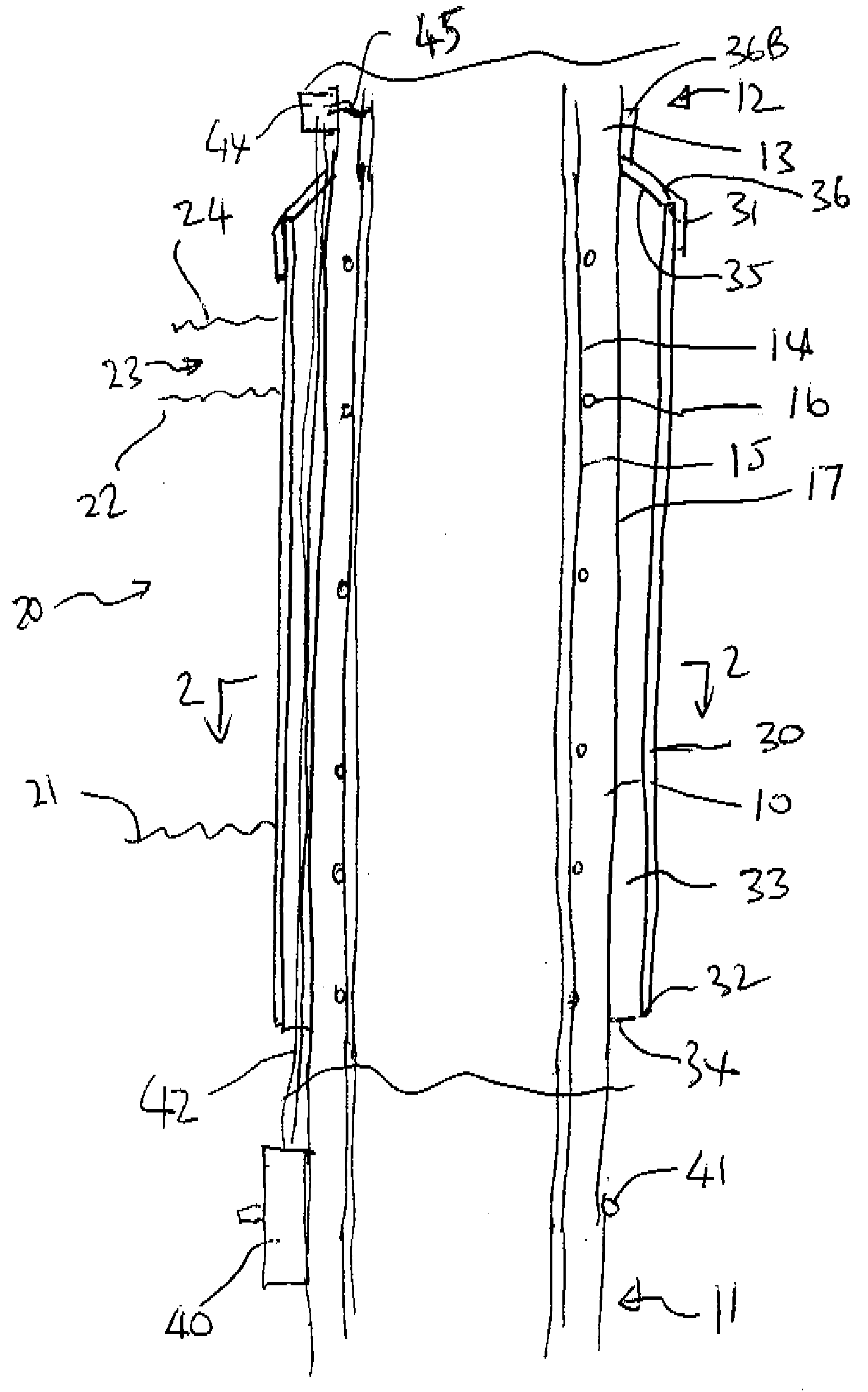
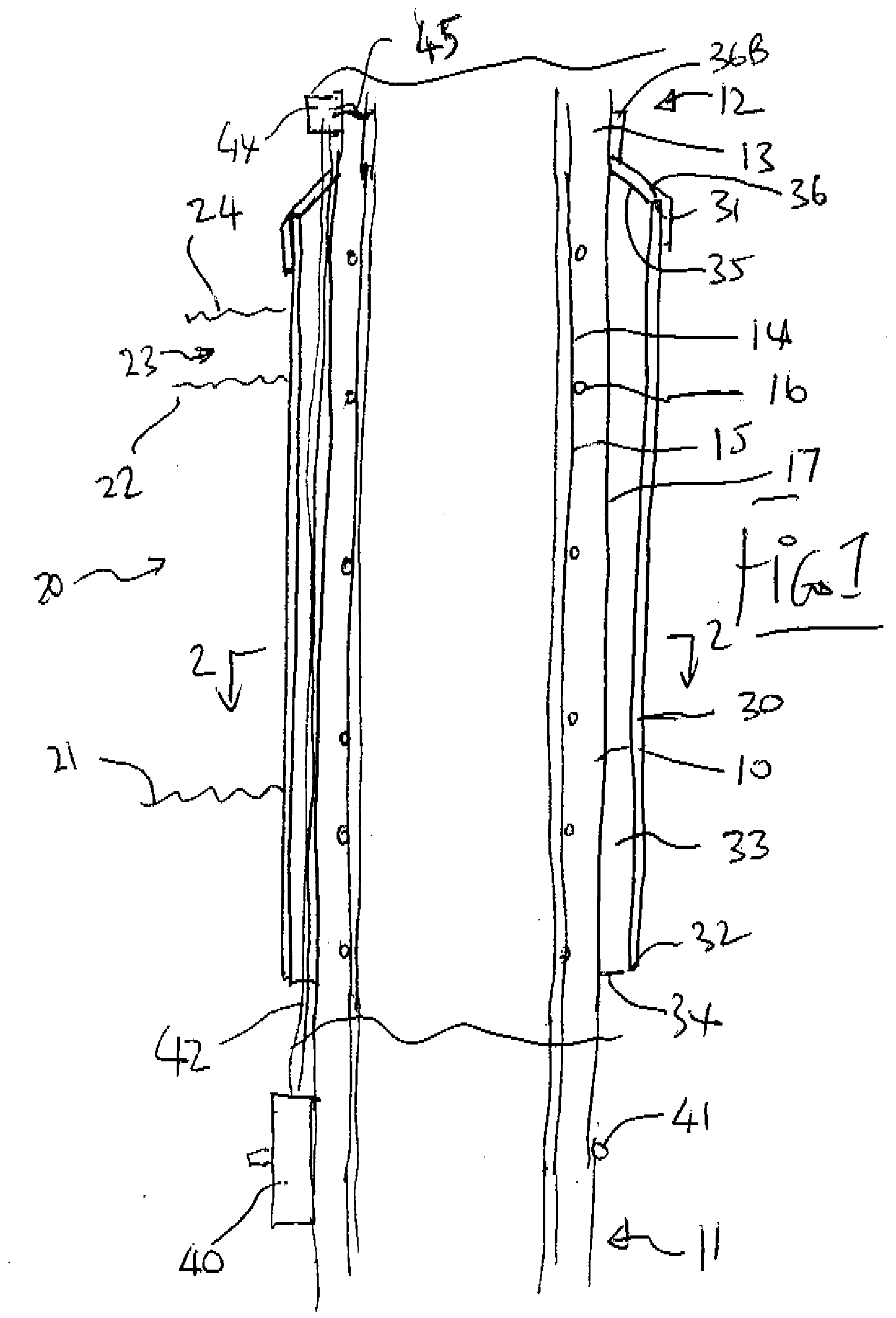
[0085]In FIG. 1 is shown a conventional reinforced concrete column mounted in water so that the column 10 has a bottom end generally indicated at 11 mounted on a suitable support in the water with the upper end 12 arranged to carry a structure to be supported by the column. Typical columns of this type are formed of a concrete body 13 within which is cast steel reinforcing members generally indicated at 14. These include vertical longitudinal members 14 and transverse or peripheral hoops or ties 16. The steel reinforcement is located inside the column just under the outside surface 17 of the column.

[0086]The column is illustrated as being mounted so that a part of the length of the column is located in the inter-tidal zone generally indicated at 20 with a low tide mark indicated at 21 and a high tide mark indicated at 22. Above the high tide mark is a splash zone 23 with an upper location 24. It will of course be appreciated that the tides vary and the amount of splash height varies...


PUM


Abstract

Corrosion of steel in a concrete structure such as a column in sea water occurs primarily at the zone which is subject to a wetting and drying action and is inhibited using cathodic protection by attaching to the column at the zone an impervious sealed sleeve which carries no anode itself but which cooperates with an anode body in the water below the sleeve. The sleeve acts to inhibit permeation of oxygen through the concrete to the steel and at the same time acts to promote transfer of current from the anode through the concrete under the sleeve by preventing drying by preventing moisture escape. An anode arrangement may be provided only at the top of the sleeve to consume oxygen in that area. The sleeve may be applied over a layer of grout. The top edge surface of the grout may be sealed from the sleeve to the column.

Description

[0001]This invention relates to a method of cathodic protection of a concrete structure having a part in contact with a wetting medium and a part above the medium, such as a column within a salt water environment.BACKGROUND OF THE INVENTION[0002]Concrete structures such as columns in salt water tend to corrode at the location just above the salt water in the inter-tidal zone where the column is subject to wetting and drying.[0003]One solution to this problem is to surround the column with a jacket containing a layer of grout within which is buried or located a sacrificial anode as a mesh or layer surrounding the column. This anode is electrically connected to the steel in the column to set up an electric current through the connection and an ionic current through the salt water electrolyte and the concrete from the anode to the steel to tend to inhibit the corrosion of steel in favour of the corrosion of the sacrificial anode.[0004]An example of an arrangement of this type is shown ...

Claims


Application Information

Patent Timeline
IPC IPC(8): C23F13/00
CPCC23F13/02C23F2213/31C23F2201/02C23F13/06
Inventor WHITMORE, DAVID
Owner WHITMORE DAVID
Why Eureka
Try Eureka