This helps you quickly interpret patents by identifying the three key elements:
Problems solved by technology
Method used
Benefits of technology
[0015]The present invention provides for a single cavity molding device wherein upon placement of a golf ball sub-assembly into the cavity mold and then a urethane or urea cover material cast into the cavity mold, a cover is formed herein by compression molding. The molding device utilizes a pair mold halves, each having a backing plate and mold frame and they each house a hemispherical cavity mold. An object of the invention is to provide for compression molding using only a single cavity and without the need of bolts to secure the mold halves together. The invention utilizes a plurality of clamping pins, each pin having its top portion reciprocally disposed in a recess of the backing plate of the top mold. Double spring Belleville washers are integral to the top portion of each clamping pin and when an outside force is applied, the washers are compressed placing the device into a controlled state of tension. To maintain the compressive force for the duration of the molding cycle, the
Problems solved by technology
Balata-covered balls, however, are easily damaged, and thus lack the durability required by the average golfer.
However, while ionomer-covered golf balls possess virtually cut-proof covers, the spin and feel are inferior compared to balata-covered balls.
Once these two ingredients are combined, the polyurea is formed, and thus the ability to vary the physical properties of the composition is limited.
Some of the problems that exist in multi-cavity molds are inherent in the inability to heat or cool each cavity uniformly.
This is primarily caused by the uneven contact the fluid makes as it travel through the mold frame.
Also, in multi-cavity molds, some of the cavities wear out prior to others creating inconsistent product
Method used
Image
Click on the blue label to locate the original text in one second.
Reading with bidirectional positioning of images and text.
Examples
Embodiment Construction
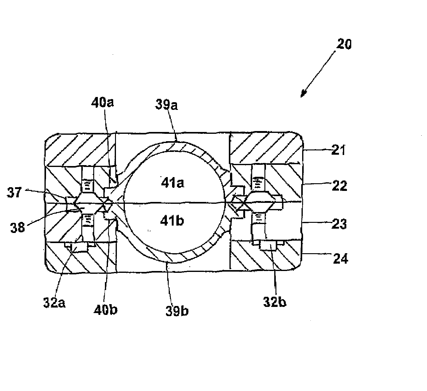
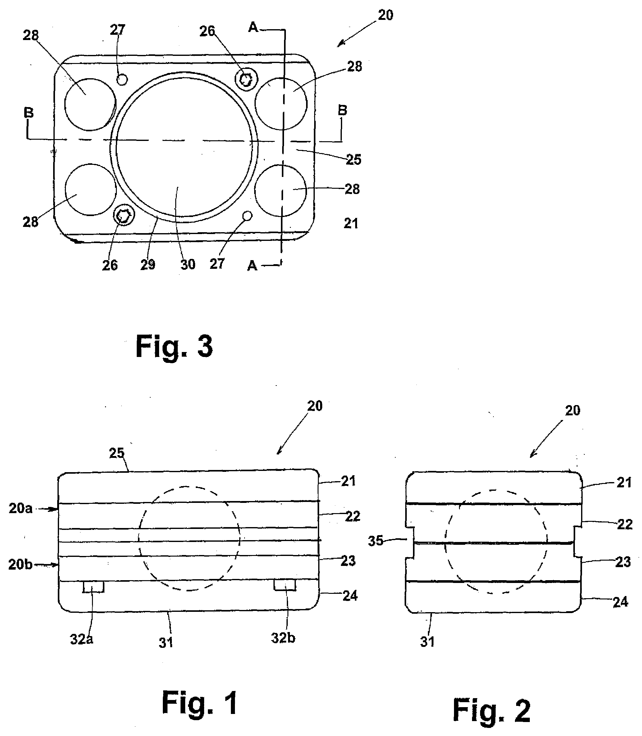
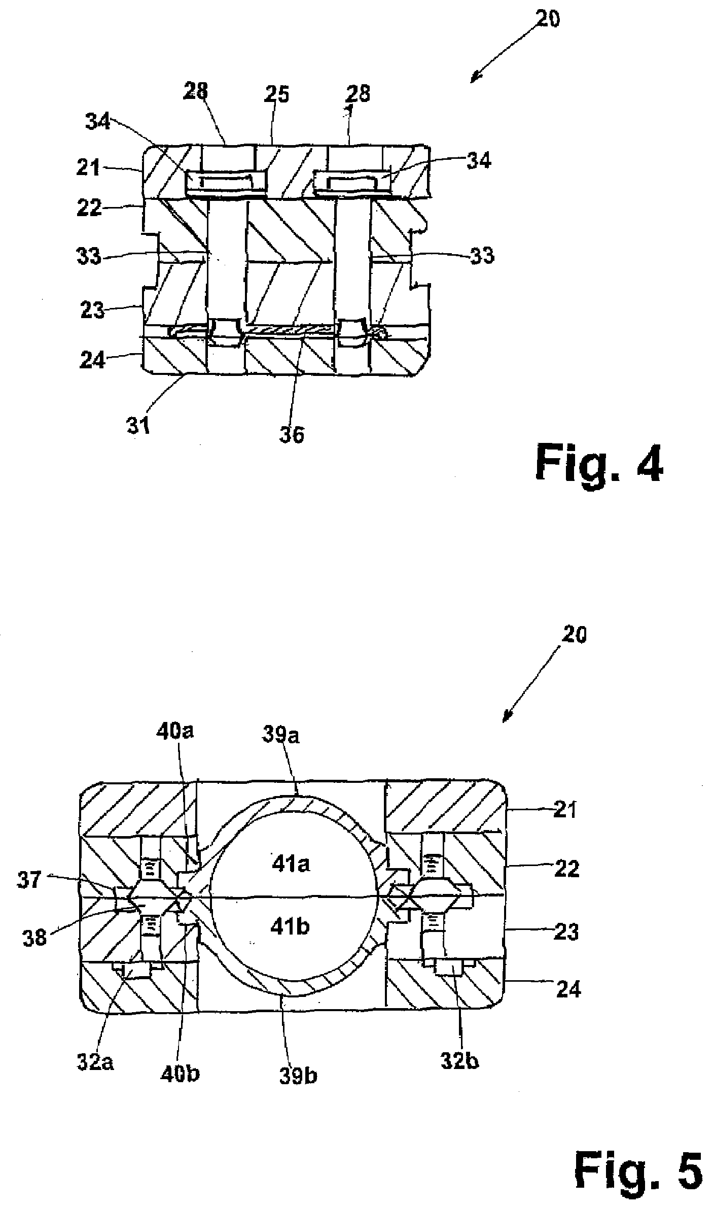
[0039]There are conventional multi-cavity mold frames such as referenced by U.S. Pat. No. 6,439,873, which are used for casting a layer for a golf ball. Typically, these type molds are used to cast polyurethane covers on a golf ball sub-assembly (not shown). The Acushnet Company (assignee of this application) has for many years used multi-cavity molds that provide four cavities in a mold frame. A significant problem of these compression molds is the inability to achieve equally distributed positive clamping force on the golf balls being formed. The closure of these type molds is accomplished by using vertical pistons, torque clutch / motor assembly, and an assembly of belts, pulleys and torque bits. Each four cavity mold has four bolts to fasten the mold halves together. The constant bolting and unbolting to open and close the mold halves causes an uneven wear and tear of the bolts creating a significant variation in torque between the bolts, resulting in a major source of contaminati...
PUM
Property
Measurement
Unit
Mass
aaaaa
aaaaa
Force
aaaaa
aaaaa
Size
aaaaa
aaaaa
Abstract
The present invention is an improved single cavity molding device and method for compression molding polyurethane, polyurea or polyurethane/polyurea hybrid covers over golf ball sub-assemblies. The device utilizes top and bottom mold-halves and is particularly novel in that it does not require the use of bolts to secure the mold-halves. The molding device utilizes a pair mold halves, each having a backing plate and mold frame for housing a hemispherical cavity mold. The invention utilizes a plurality of clamping pins, each pin having its top portion reciprocally disposed in a recess of the backing plate of the top mold. Double spring Belleville washers are coupled to the top portion of each clamping pin and upon the application of a vertical force, the washers are compressed to place the device in a controlled state of tension and also cause the clamping pins, to move downward into a locking position with slidable retainers to therein maintain a compressive force of at least 384 pounds on the golf ball sub-assembly for the molding process. Upon completion of the molding process, a vertical force is applied to the top of the clamping pins wherein they are moved out of a coupled relationship with the engagement loops, and with a coordinating horizontal biasing, the retainers are moved away from the pins, whereby the mold-halves may be then opened and a covered golf ball removed.
Description
FIELD OF THE INVENTION[0001]This invention generally relates to the manufacture of golf balls, and more particularly, to a single cavity mold for compression molding polyurethane, polyurea, or polyurea / polyurethane hybrid covers over golf ball sub-assemblies.BACKGROUND OF THE INVENTION[0002]The present invention relates to an improvement to molds, such as that disclosed in U.S. Pat. Nos. 6,936,205, 7,135,138, 7,041,007, 7,041,245, 6,644,948, and 6,439,873, all of which are assigned to the Acushnet Company and are incorporated herein by reference. A typical multi-cavity mold used for applying a thermosetting cover material is disclosed in U.S. Pat. No. 6,439,873 issued to Marshall.[0003]The covers of today's golf balls are made from a variety of materials, but predominately they are either of a thermoplastic material such as SURLYN® and IOTEK® or a thermoplastic material such as polyurethane. In the past, premium golf balls were covered by a balata material. Balata is a natural or sy...
Claims
Application Information
Patent Timeline
Application Date:The date an application was filed.
Publication Date:The date a patent or application was officially published.
First Publication Date:The earliest publication date of a patent with the same application number.
Issue Date:Publication date of the patent grant document.
PCT Entry Date:The Entry date of PCT National Phase.
Estimated Expiry Date:The statutory expiry date of a patent right according to the Patent Law, and it is the longest term of protection that the patent right can achieve without the termination of the patent right due to other reasons(Term extension factor has been taken into account ).
Invalid Date:Actual expiry date is based on effective date or publication date of legal transaction data of invalid patent.