Check patentability & draft patents in minutes with Patsnap Eureka AI!

Motor Used to Drive Optical Elements

Inactive Publication Date: 2008-08-28
SHENZHEN HANS PRECISION MECHATRONICS
View PDF8 Cites 4 Cited by
  • Summary
  • Abstract
  • Description
  • Claims
  • Application Information

AI Technical Summary

Benefits of technology

[0005]An object of the present invention is to provide a motor used to drive optical elements which is controlled by a encoder so as to eliminate the instability of the system caused by the drift of the conventional transducer. At the same time, it is in order to improve the motor's capability so as to improve the system's response, positioning and repeatability.
[0017]As described hereinabove, the invention utilizes the encoder so as to eliminate the drift caused by transducer and also utilizes the multipole motor to drive the load so that the load will move fast and smoothly. The capability of the system is improved greatly.

Problems solved by technology

However, the accuracy, the repeatability and the stability of the motor are restricted greatly for the drift of the transducer.
The motor's response / (the response of the motor) is restricted because of the small ratio of torque and inertia.

Method used


Image

  • Motor Used to Drive Optical Elements
  • Motor Used to Drive Optical Elements
  • Motor Used to Drive Optical Elements

Examples


Embodiment Construction

[0026]Detailed description will hereunder be given of the preferred embodiment of a motor used to drive optical elements according to the present invention with reference to the accompanying drawings.

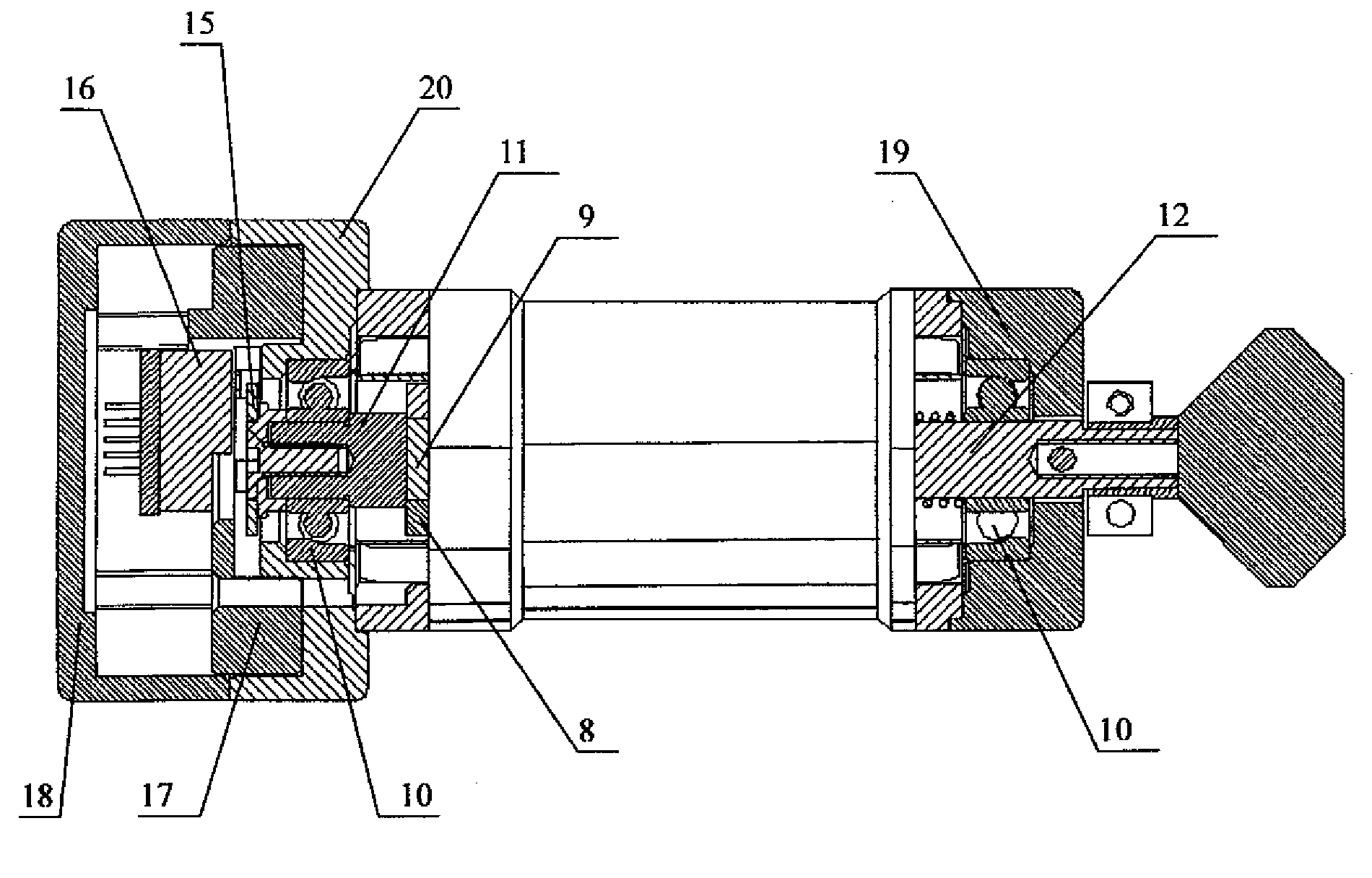
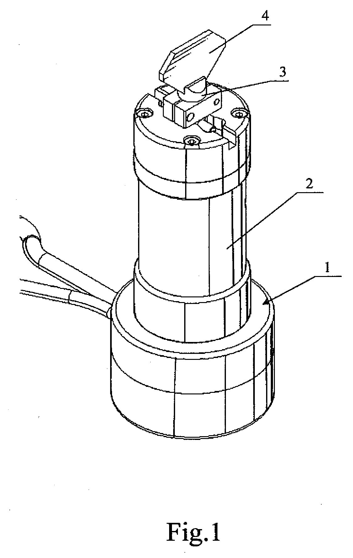
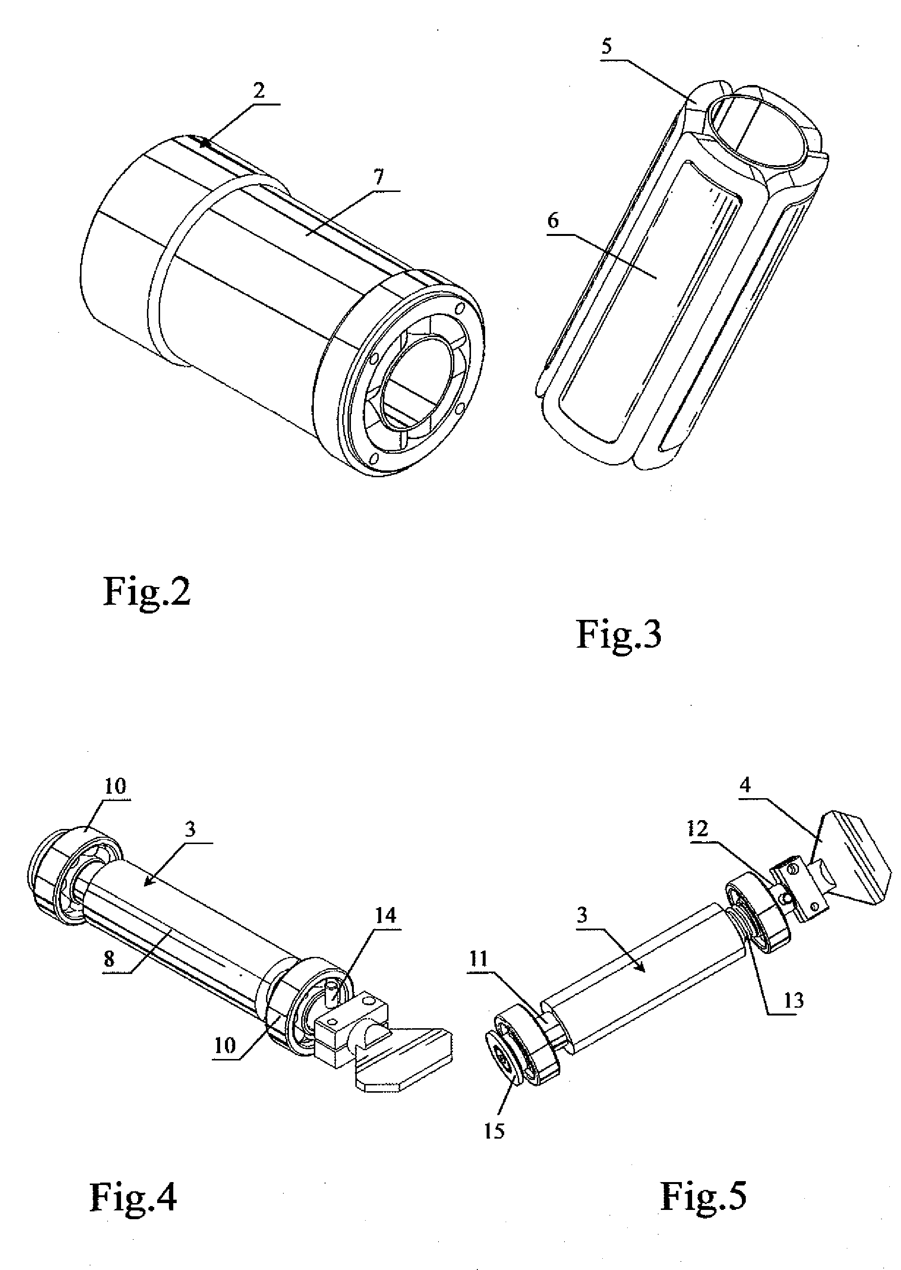
[0027]As show in FIG. 1 to FIG. 6, the motor 1 used drive optical elements includes a stator 2 and a rotor 3 revolved relative to the stator 2. The stator 2 includes coils 5, a bobbin 6 and a magnetic yoke 7. The bobbin 6 is made of nonmagnetic material. A plurality of slots are defined on the bobbin 6. Each coil 5 is placed into the slot respectively after it is shaped and the coils 5 form the motor winding by connected in certain sequence. The coils 5 and the bobbin 6 are inserted into the magnetic yoke 7 and shaped together by pouring epoxy resin. The rotor 3 includes a plurality of magnets 8, a shaft 9 and a pair of bearings 10. The magnets 8 whose polarity is alternately arranged are affixed on the shaft 9. The shaft 9 includes a main body (not show in the FIGS) which is covered by...


PUM


Abstract

A motor used to drive optical elements includes a stator, a rotor revolved relative to the stator, and a feedback apparatus used to sense the position of the rotor. The feedback apparatus is an encoder. The invention utilizes such described structure so as to eliminate the system's instability caused by the drift of the conventional capacitive type transducer or an inductance type transducer. Moreover, the response of the motor used to drive optical elements has been improved greatly by utilizing multipole motor.

Description

BACKGROUND OF THE INVENTION[0001]1. Field of the Invention[0002]The present invention relates to a motor, and in particular to a motor used to drive optical elements such as mirrors for the purpose of guiding light beams in laser marker, scanners or other systems which are similar to these.[0003]2. The Related Art[0004]A motor used to drive optical elements usually has different structure and configuration. Traditionally, the position feedback apparatus of the motor used to drive optical elements utilizes a capacitive type transducer or an inductance type transducer. However, the accuracy, the repeatability and the stability of the motor are restricted greatly for the drift of the transducer. Moreover, the motor includes two magnetic poles and the motor is supported by ball bearings. The motor's response / (the response of the motor) is restricted because of the small ratio of torque and inertia. And also, the running accuracy is influenced by the low axial stiffness.SUMMARY OF THE IN...

Claims


Application Information

Patent Timeline
IPC IPC(8): H02K11/00H02K7/08
CPCH02K33/16H02K11/0015H02K11/21
Inventor GAO, YUN-FENGLIAO, YOU-YONGWANG, GUANG-NENGFU, XIAO-HUI
Owner SHENZHEN HANS PRECISION MECHATRONICS
Features
  • R&D
  • Intellectual Property
  • Life Sciences
  • Materials
  • Tech Scout
  • Unparalleled Data Quality
  • Higher Quality Content
  • 60% Fewer Hallucinations
Learn More