
Free-standing nanowire sensor and method for detecting an analyte in a fluid

a free-standing, nanowire technology, applied in the direction of instruments, chemical methods, analysis using chemical indicators, etc., can solve the problems of low yield of such devices with good electrical contacts, high surface-to-volume ratios of nanowires, and high cost and time-consuming

Inactive Publication Date: 2008-08-28
HEWLETT PACKARD DEV CO LP
View PDF3 Cites 70 Cited by
  • Summary
  • Abstract
  • Description
  • Claims
  • Application Information

AI Technical Summary

Benefits of technology

[0007]It has been recognized that it would be advantageous to develop a chemical or biological sensor that is much more sensitive than the standard sensors available today.
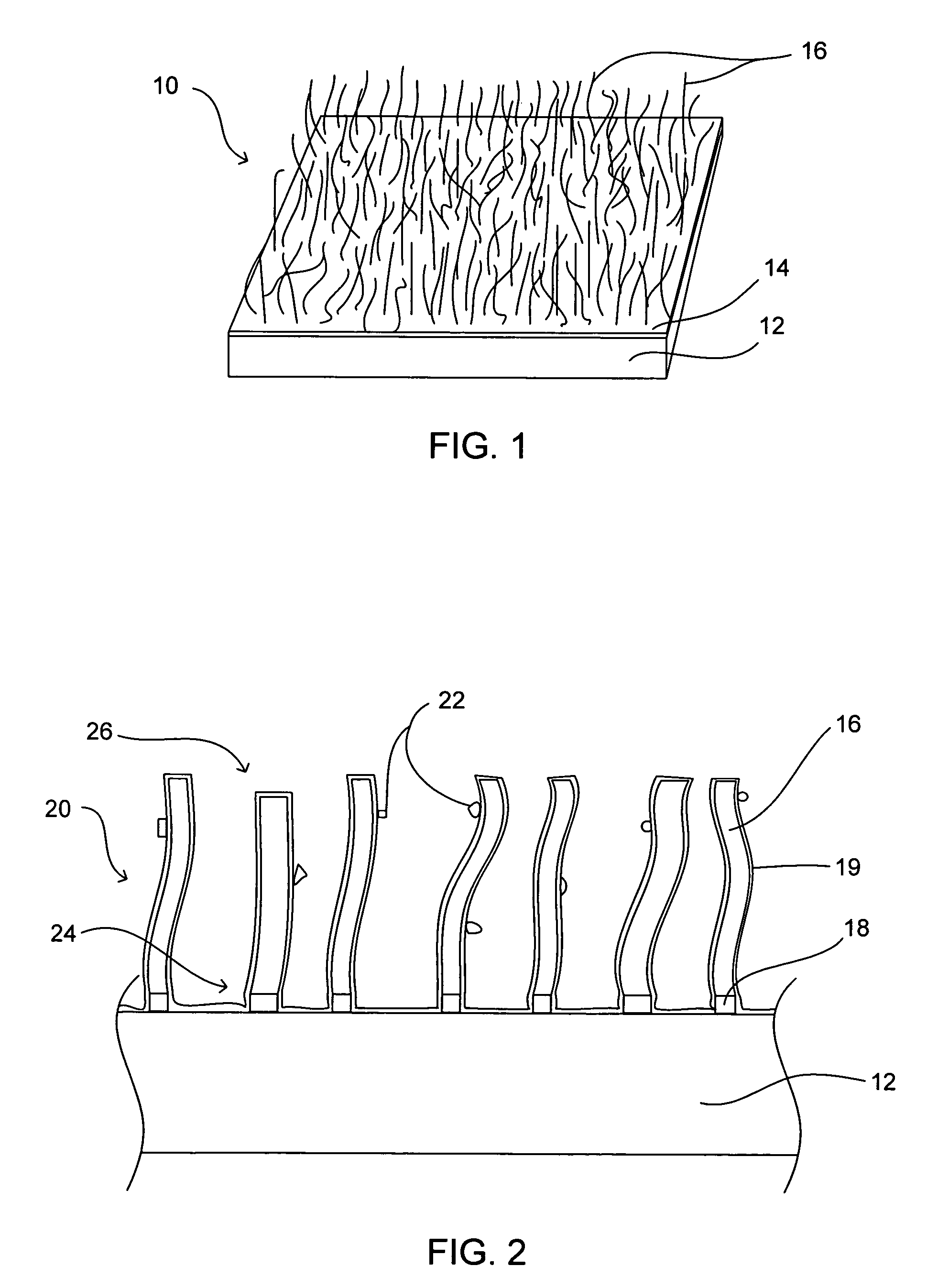
[0011]Once grown, or as part of the growing process, the array of free-standing nanowires can be functionalized with a composition that is interactive with a predetermined analyte. For example, functionalization can be by chemical attachment of a receptor or an oxidizing or reducing agent. Alternatively, functionalization can be by deposition of a desired material onto the surface of the nanowires. In one embodiment, the deposited composition can be a dielectric coating. Thus, when an individual nanowire comes in contact with an analyte, the analyte can stick to the dielectric coating by attraction to the nanowire (through the coating), providing a capacitive effect. Alternatively, deposited or chemically attached coatings can be configured to be chemically reactive with an analyte.

Problems solved by technology

While ChemFETs exploit the same physical principles for detection as nanowires, they require large planar surface areas over the FET channel and lack the extreme sensitivity and discrimination enabled by the high surface-to-volume ratios of nanowires.
Disadvantages of this approach include the requirement of placing and contacting individual nanowires which is expensive and time consuming, and that the yield of such devices with good electrical contacts may be low.
Devices that are based on a single nanowire are also not very sensitive and can provide spurious signals.

Method used


Image

  • Free-standing nanowire sensor and method for detecting an analyte in a fluid
  • Free-standing nanowire sensor and method for detecting an analyte in a fluid
  • Free-standing nanowire sensor and method for detecting an analyte in a fluid

Examples


Embodiment Construction

)

[0028]Reference will now be made to the exemplary embodiments illustrated in the drawings, and specific language will be used herein to describe the same. It will nevertheless be understood that no limitation of the scope of the invention is thereby intended. Alterations and further modifications of the inventive features illustrated herein, and additional applications of the principles of the inventions as illustrated herein, which would occur to one skilled in the relevant art and having possession of this disclosure, are to be considered within the scope of the invention. It is also to be understood that the terminology used herein is used for the purpose of describing particular embodiments only. The terms are not intended to be limiting.

[0029]It must be noted that, as used in this specification and the appended claims, the singular forms “a,”“an,” and “the” include plural referents unless the content clearly dictates otherwise.

[0030]“Free-standing nanowires” or “array of free-...


PUM

PropertyMeasurementUnit
lengthaaaaaaaaaa
thicknessaaaaaaaaaa
aspect ratioaaaaaaaaaa

Abstract

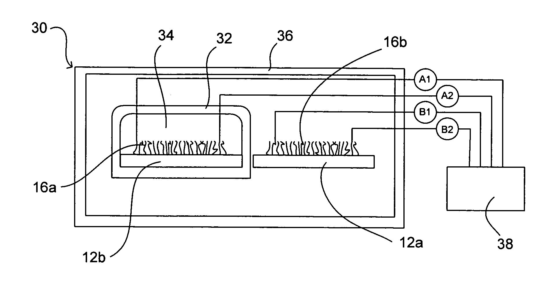
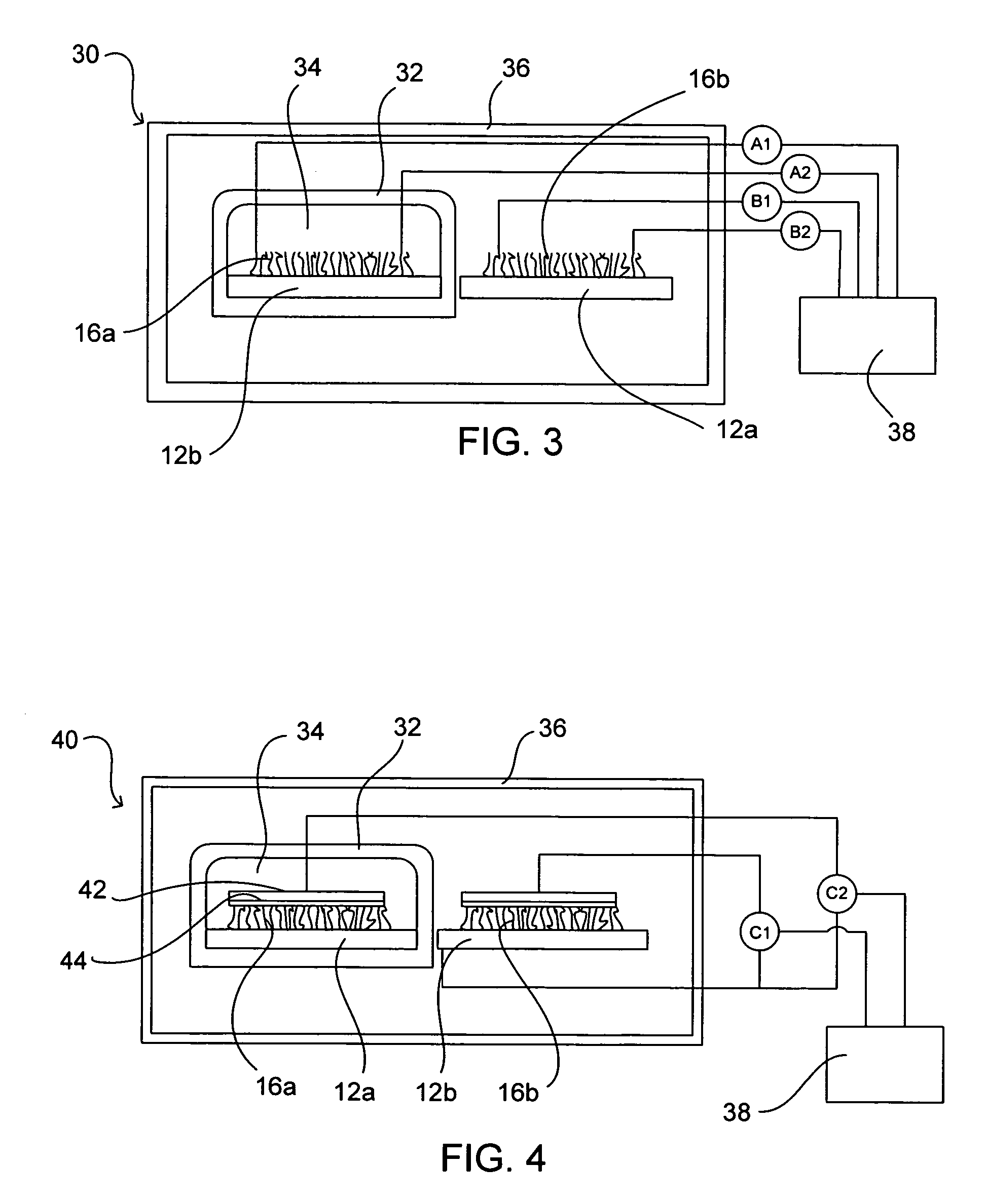
A sensor device and method for detecting the presence of an analyte in a fluid solution are disclosed. The sensor device system can comprise a substrate and an array of free-standing nanowires attached to the substrate. The array can include individual free-standing nanowires wherein each of the individual free-standing nanowires have a first end and a second end. The first end can, in some embodiments, be attached to the substrate and the second end unattached to the substrate. Such individual free-standing nanowires are configured for electrical communication with other individual free-standing nanowires through the first end. A chip or computer can be electrically coupled to the array of free-standing nanowires for receiving electrical information from the array of free-standing nanowires. In some embodiments a power source can be used to send current through the nanowire array.

Description

[0001]The present application is a divisional of U.S. patent application Ser. No. 10 / 309,608, filed Dec. 3, 2002, which is hereby incorporated by reference.FIELD OF THE INVENTION[0002]The present invention relates generally to chemical and biological analysis. More particularly, the present invention relates to free-standing nanowire sensors.BACKGROUND OF THE INVENTION[0003]Chemical analysis and the identification of biological materials has long been the domain of analytical biology, chemistry and physics. The methods used often require cumbersome laboratory instrumentation in a centralized laboratory and long sampling and analysis times. However, over the last few decades, the increasing awareness and concern regarding factors that influence health, safety, appliance performance, and the environment has created a demand for user-friendly technologies capable of detecting, identifying, and monitoring chemical, biological, and environmental conditions in real-time. In response to th...

Claims


Application Information

Patent Timeline
Patent Type & Authority Applications(United States)
IPC IPC(8): G01N27/22G01N27/02B82B1/00G01N37/00G01N27/00G01N27/04G01N27/06
CPCY10T436/114998G01N27/3278
Inventor STASIAK, JAMESMCCLELLAND, PAUL H.HACKLEMAN, DAVID E.PEASE, GRANTWILLIAMS, R. STANLEYPETERS, KEVIN
Owner HEWLETT PACKARD DEV CO LP
Learn More