METHOD AND TESTING EQUIPMENT FOR LEDs AND LASER DIODES

a technology of leds and laser diodes, applied in the field of testing and diagnostic equipment, can solve problems such as difficulty, and achieve the effect of simple and quick implementation of procedures

Active Publication Date: 2008-08-28
EPISTAR CORP
View PDF7 Cites 35 Cited by
  • Summary
  • Abstract
  • Description
  • Claims
  • Application Information

AI Technical Summary

Benefits of technology

[0004]In view of the foregoing disadvantages inherent in the known types of testing procedures, this invention provides an improved testing method for LEDs and equipment for the same. As such, the present invention's general purpose is to provide a new and improved method that is non-invasive, non-destructive, and having a simple and quickly implemented procedure.

Problems solved by technology

This requires separation of the effect of serial resistance, which is difficult to do.

Method used


Image

  • METHOD AND TESTING EQUIPMENT FOR LEDs AND LASER DIODES
  • METHOD AND TESTING EQUIPMENT FOR LEDs AND LASER DIODES
  • METHOD AND TESTING EQUIPMENT FOR LEDs AND LASER DIODES

Examples


Embodiment Construction

[0042]With reference now to the drawings, the preferred embodiment of the LED testing method and apparatus is herein described. It should be noted that the articles “a”, “an” and “the”, as used in this specification, include plural referents unless the content clearly dictates otherwise.

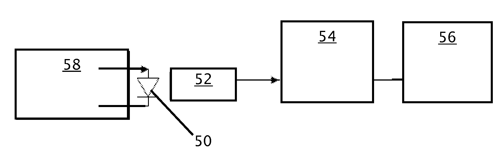
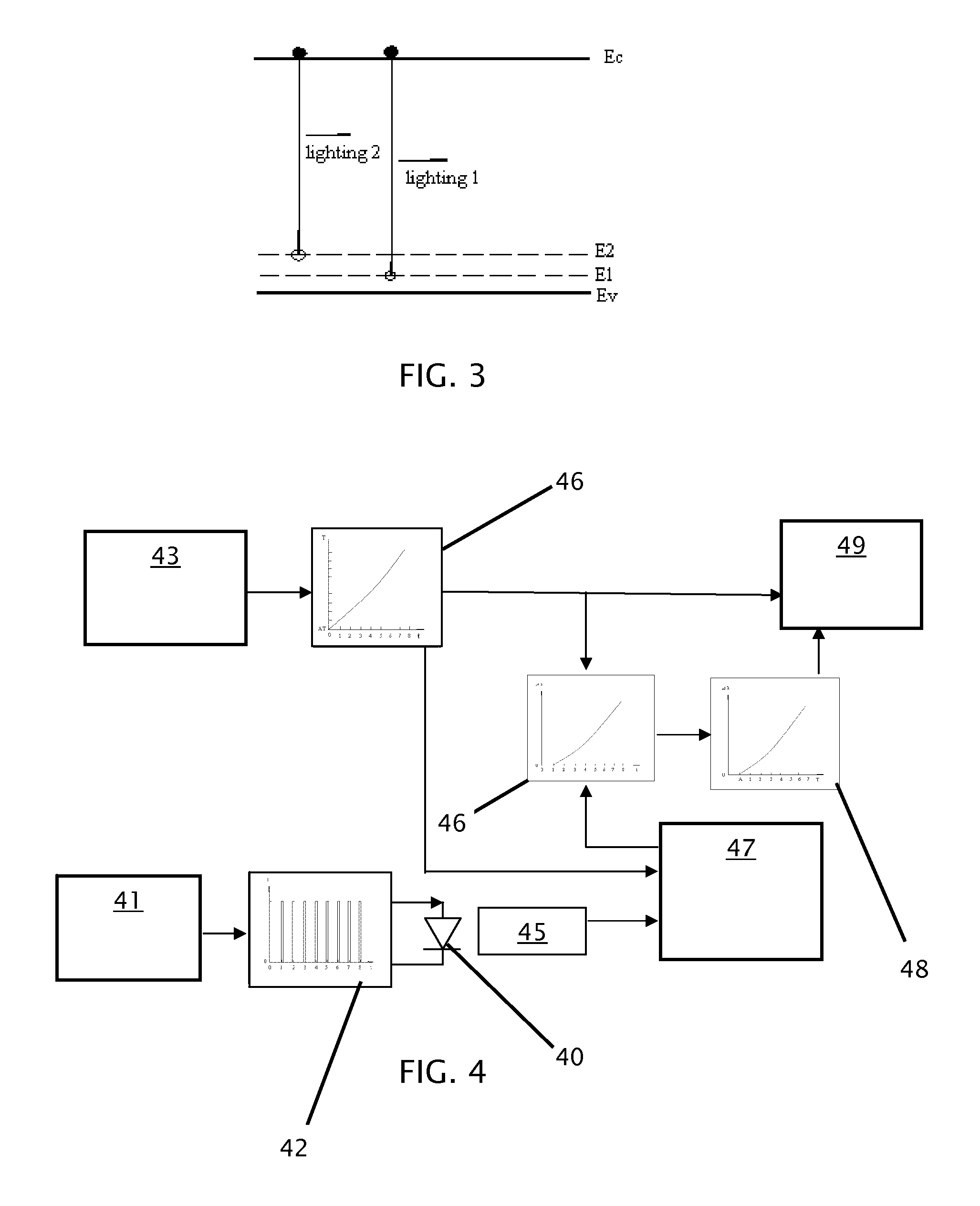
[0043]The first step in the method according to the present invention is to determine the function of the peak wavelength of the LED as a function of temperature, so that the function may be used in later testing. The function may be determined with direct observation of an LED in an apparatus such as the one depicted schematically in FIG. 4. In practice, an LED 40, of a known type may be connecter to a power supply 41 and located in a heat chamber 43. The power supply 41 then drives the LED 40 with a constant forward pulse current 42 (FIG. 10), activating it and guaranteeing that carrier injection level is constant. Data regarding the spectrum is gathered by a detector 45 and compiled by a spectrome...


PUM

PropertyMeasurementUnit
temperatureaaaaaaaaaa
peak wavelengthaaaaaaaaaa
wavelengthaaaaaaaaaa

Abstract

The present invention is a non-invasive method and associated apparatus for determining the junction temperature for an LED or laser diode (collectively “LED”). First a sample LED is placed in a heat chamber and the change of the LED's peak wavelength is recorded over time, as is the change in the temperature in the heat chamber. Since the heat chamber supplies the major component to the junction temperature, dwarfing the other components, it is a reasonable proxy for true junction temperature. The data is compiled to determine change of peak wavelength as a function of temperature and that function can then be used to determine junction temperature of similar LEDs that are installed in a system or manufactured. The invention may also be used to measure other useful data, such as power, output power changing with the junction temperature and intensity of the LED over time and may be used to estimate failure rate.

Description

FIELD OF THE INVENTION[0001]The present invention relates to the field of testing and diagnostic equipment and more particularly relates to a method and equipment for testing LEDs and laser diodes.BACKGROUND OF THE INVENTION[0002]Junction temperature affects the performances of both light emitting diodes (LEDs) and laser diodes in many ways. For simplicity, this Application and the appended claims shall use the terms “LED” and “diode” to include both LEDs and laser diodes and the terms should be read as including both types of diodes without limiting the Application or the claims to just LEDs. The light output wavelength, spectrum, power magnitude, and diode reliability are all directly dependent on the junction temperature. Thus, the thermal design of a diode itself and the packaging in which a diode is encased become crucial to the overall performance of the device. The diode junction temperature is generated from three main components: the internal thermal resistance of the diode...

Claims


Application Information

Patent Timeline
Patent Type & Authority Applications(United States)
IPC IPC(8): G01K7/00
CPCG01K7/01G01K11/00G01R31/2635G01K15/005G01K15/00
Inventor CAO, DESENLIN, ZHAO-HUI
Owner EPISTAR CORP
Why Eureka
Try Eureka