Tapered roller bearing

a technology of tapered roller bearings and roller bearings, which is applied in the direction of rolling contact bearings, shafts and bearings, rotary bearings, etc., can solve the problems of increasing the possibility of seizure, and achieve the effects of reducing torque loss, improving seizure resistance, and efficient supply of lubricating oil

Inactive Publication Date: 2008-08-28
JTEKT CORP
View PDF2 Cites 13 Cited by
  • Summary
  • Abstract
  • Description
  • Claims
  • Application Information

AI Technical Summary

Benefits of technology

[0008]The invention has been made in view of the problems described above, and an object of the invention is to provide a tapered roller bearing that can supply lubricating oil efficiently

Problems solved by technology

In particular, when the amount of lubricating oil supply is further decreased in order to decrease the torque loss of the tapered roller to realize a mechanical device of low torque loss, the amount of lubricating oil supply to t

Method used


Image

  • Tapered roller bearing
  • Tapered roller bearing
  • Tapered roller bearing

Examples


embodiment 1

[0052]A first embodiment of the invention will be described with reference to FIGS. 1 to 4.

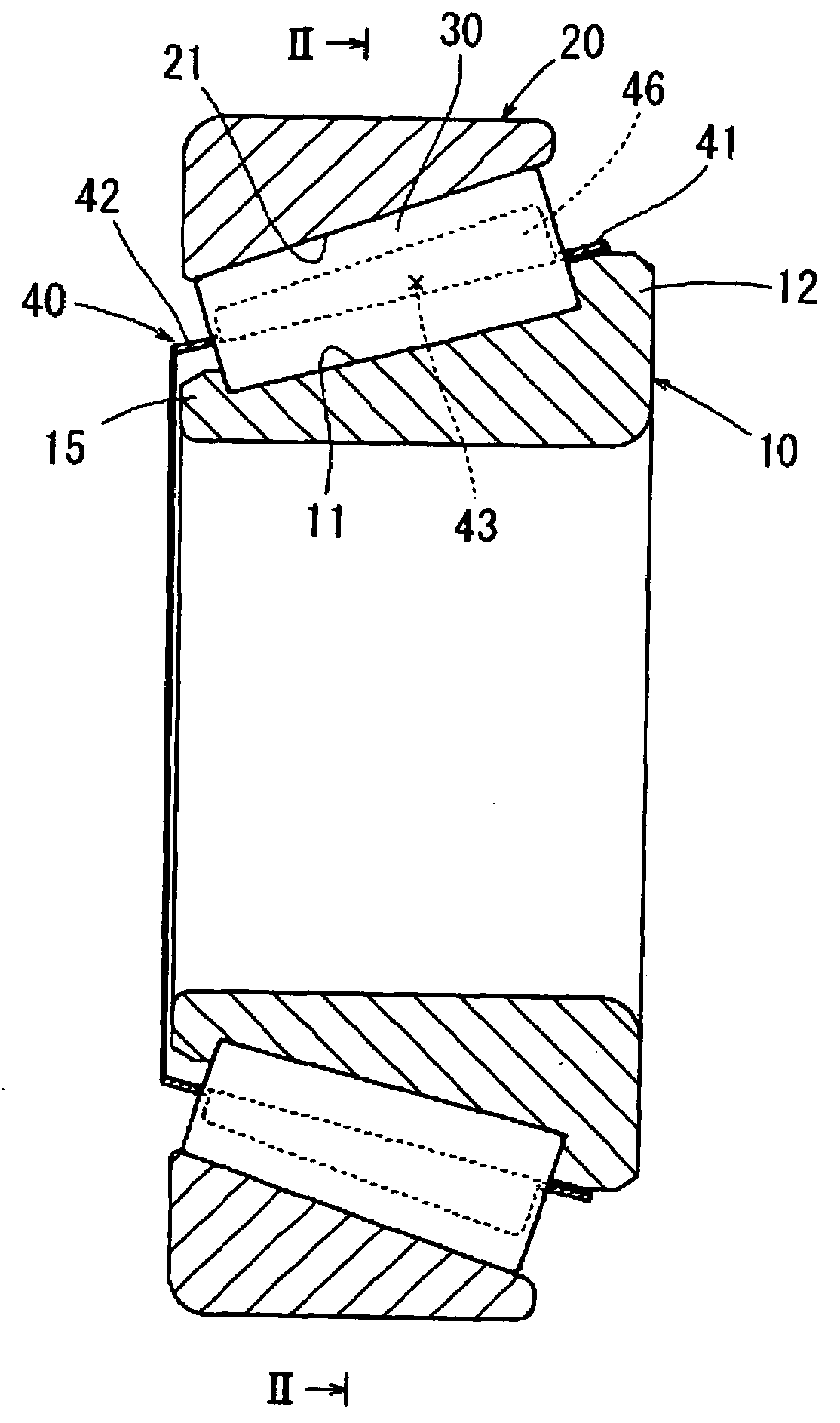
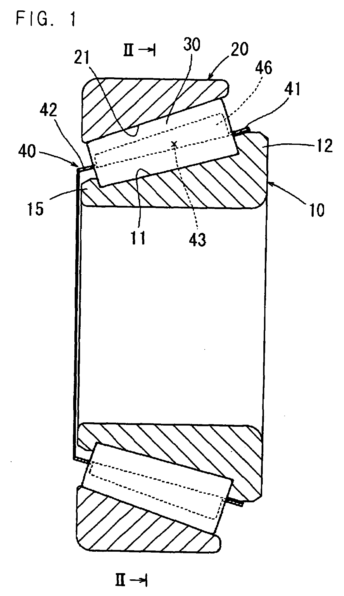
[0053]FIG. 1 is a longitudinal sectional view of a tapered roller bearing according to a first embodiment of the invention. FIG. 2 is a transversal sectional view along the line II-II of FIG. 1. FIG. 3 is an enlarged, longitudinal sectional view showing the attachment state of an inner ring, an outer ring, a tapered roller, and a cage. FIG. 4 is a transversal sectional view along the line IV-IV of FIG. 3.

[0054]As shown in FIGS. 1 and 2, a tapered roller bearing includes an inner ring 10, an outer ring 20, a plurality of tapered rollers 30, and a cage 40.

[0055]The inner ring 10 has a tapered raceway surface 11 formed on an outer peripheral surface, and large and small ribs 12 and 15 are formed at opposite end portions of the raceway surface 11.

[0056]The outer ring 20 has a tapered raceway surface 21 formed on an inner peripheral surface so as to oppose the raceway surface 11 of the inner ring 1...

embodiment 2

[0071]A second embodiment of the invention will be described with reference to FIGS. 5 to 8.

[0072]FIG. 5 is a longitudinal sectional view of a tapered roller bearing according to a second embodiment of the invention. FIG. 6 is a transversal sectional view along the line II-II of FIG. 5. FIG. 7 is an enlarged, longitudinal sectional view showing the attachment state of an inner ring, an outer ring, a tapered roller, and a cage. FIG. 8 is a transversal sectional view along the line IV-IV of FIG. 7.

[0073]In a tapered roller bearing of the second embodiment, the same elements as the tapered roller bearing of the first embodiment will be denoted by the same reference numerals, and descriptions thereof will be omitted.

[0074]As shown in FIGS. 5 and 6, the cage 140 retaining the plural tapered rollers 30 between the inner ring 10 and the outer ring 20 is formed by injection-molding of a synthetic resin material excellent in the heat resistant properties and the anti-abrasion properties and ...

embodiment 3

[0084]Next, a third embodiment of the invention will be described with reference to FIG. 9.

[0085]FIG. 9 is a longitudinal sectional view of a tapered roller bearing according to a third embodiment of the invention, showing the attachment state of an inner ring, an outer ring, a tapered roller, and a cage.

[0086]As shown in FIG. 9, in the third embodiment, an annular extension portion 141a is formed in the large diameter-side annular section 141 of the cage 140 and disposed adjacent to the outer peripheral surface of the large rib 12 of the inner ring 10.

[0087]Other arrangement of the third embodiment is the same as that of the second embodiment, and thus the same elements will be denoted by the same reference numerals and will not be described.

[0088]The tapered roller bearing of the third embodiment has the above-described arrangement.

[0089]The annular extension portion 141a of the large diameter-side annular section 141 of the cage 140 is disposed adjacent to the outer peripheral su...


PUM


Abstract

A tapered roller bearing includes an inner ring, an outer ring, a plurality of tapered rollers, and a cage. The cage includes a large diameter-side annular section, a small diameter-side annular section, and pillar sections connecting the large diameter-side annular section and the small diameter-side annular section and forming pockets retaining the tapered rollers. The radially inner surfaces of the pillar sections are disposed closer to the center than a pitch circle of the tapered rollers and are inclined from the small diameter-side annular section toward the large diameter-side annular section, thereby forming guide surfaces that guide lubricating oil toward the large rib. Roller holding portions are formed on side portions of the pillar sections so as to protrude along the outer peripheral surfaces of the tapered rollers to a position located at the outer side in the radial direction than the pitch circle.

Description

BACKGROUND OF THE INVENTION[0001]The present invention relates to a tapered roller bearing.[0002]According to the conventional tapered roller bearing, as shown in FIGS. 10 and 11, a plurality of tapered rollers 230 are rollably arranged between the respective raceway surfaces 211 and 221 of an inner ring 210 and an outer ring 220. The large end surfaces 232 of the plural tapered rollers 230 are slidably guided by a roller guide surface 213 of a large rib 212 of the inner ring 210. The small end surfaces 233 of the plural tapered rollers 230 are slidably guided by a roller guide surface 216 of a small rib 215 of the inner ring 210. A cage 240 having pockets 243 that retain the plural tapered rollers 230 is provided between the raceway surfaces 211 and 221.[0003]In the tapered roller bearing, the radially inner surfaces 245 of the pillar sections 244 of the cage 240 are disposed at the outer side in the radial direction than the pitch circle (PCD) A′ of the plural tapered rollers 230....

Claims


Application Information

Patent Timeline
IPC IPC(8): F16C33/36
CPCF16C33/46F16C33/4605F16C33/467F16C19/364F16C33/58F16C33/6681F16C2240/80F16C33/543F16C2300/02
Inventor SADA, TAKASHIMATSUYAMA, HIROKI
Owner JTEKT CORP
Why Eureka
Try Eureka