
Composite Nozzle Tip Method

a technology of nozzle tip and composite nozzle, which is applied in the field of injection molding systems, can solve the problems of gate stringing, inability to freeze a long time, and small amount of frozen plastic at the gate area, and achieves high thermal conductivity, high strength, and high thermal conductivity.

Inactive Publication Date: 2008-08-28
HUSKY INJECTION MOLDING SYST LTD
View PDF24 Cites 31 Cited by
  • Summary
  • Abstract
  • Description
  • Claims
  • Application Information

AI Technical Summary

Benefits of technology

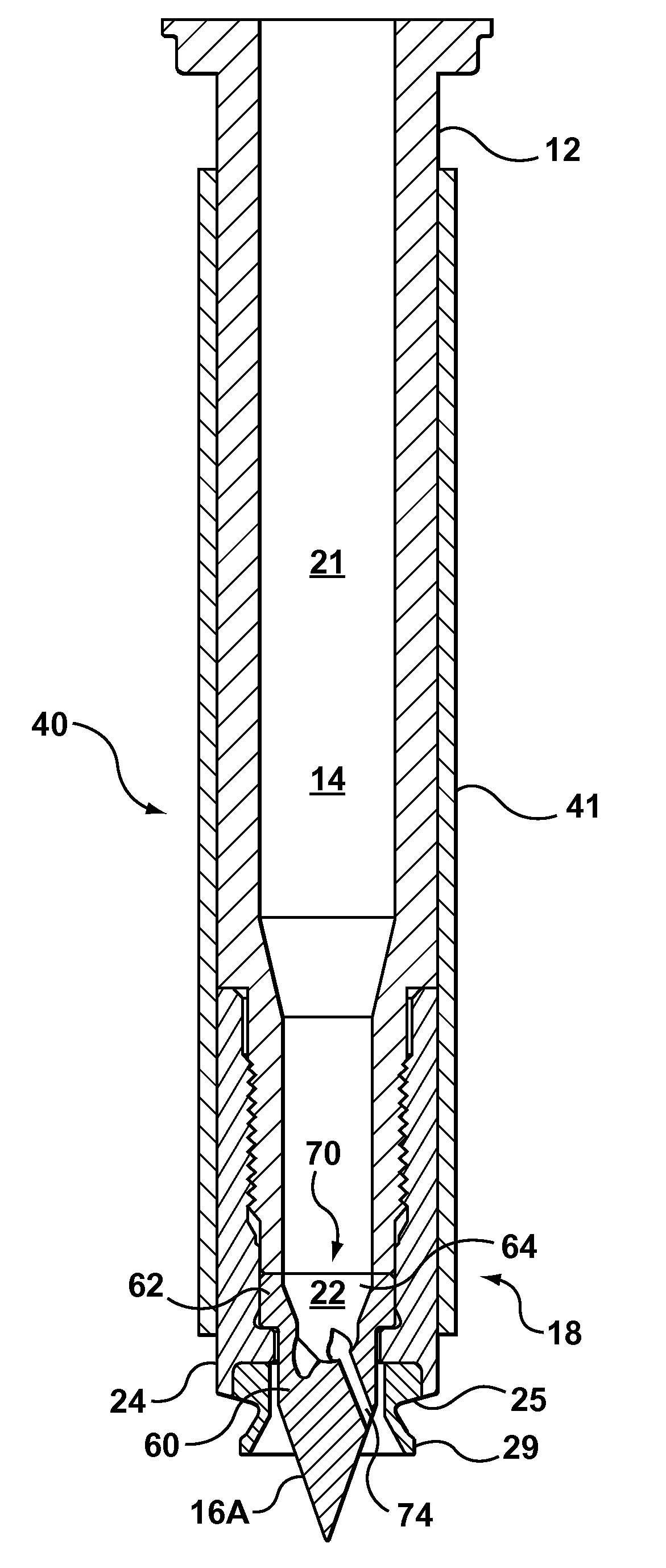
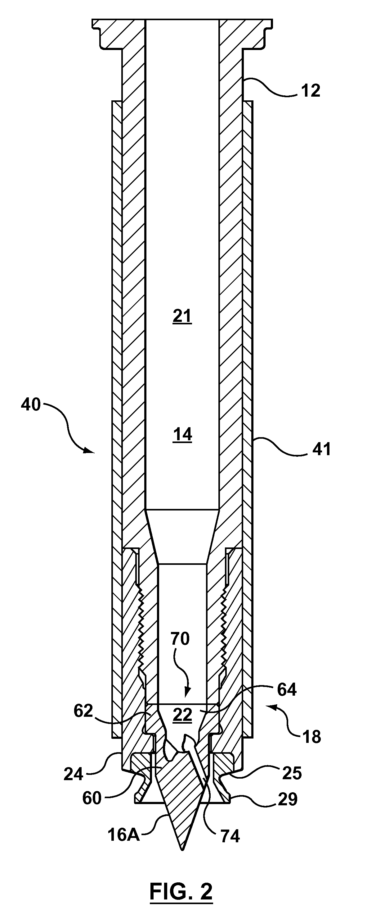
[0015]The present disclosure provides a composite nozzle tip for an injection molding assembly. The nozzle tip includes a body having a bore extending therethrough. The body is adapted for connection to the injection molding assembly. The body is formed of a precipitation hardened, high thermal conductivity material and a precipitation hardened, high strength material, which are integrally joined together to form the body. The thermal conductivity of the high thermal conductivity material is greater than the thermal conductivity of the high strength material, and at least one strength aspect of the high strength material has a value greater than the corresponding value of the same strength aspect of the high thermal conductivity material. The high thermal conductivity material and the high strength material can be precipitation hardened together under the same precipitation hardening conditions to achieve an increase in the value of at least one strength aspect of the high thermal conductivity material relative to the unhardened condition and an increase in the value of at least one strength aspect of the high strength material relative to the unhardened condition.
[0024]According to one aspect, the pre-hardened high thermal conductivity material has greater strength value of at least one strength aspect than in an unhardened condition and at least substantially maintains the strength value of the at least one strength aspect during the precipitation hardening.
[0025]According to another aspect, the high thermal conductivity material achieves, during the precipitation hardening, a further increase in the strength value of the at least one strength aspect relative to the pre-hardened material.

Problems solved by technology

Eventually the gate freezes, the mold is opened, and the part is ejected, thereby breaking the small amount of frozen plastic at the gate area.
This is known as a “gate stringing” and is unacceptable because the plastic string must be removed from the part in a subsequent operation, or the part scrapped.
Waiting a long time for the gate to freeze is also unacceptable because it adds time to the molding cycle, which is desired to be as short as possible to optimize system productivity.
If the tip is not hot enough, the gate may not open and injection will not occur, or the gate will freeze too soon causing poor-quality parts.
If the operating window is narrow, it may be difficult for molds with multiple cavities to consistently make good parts in all cavities because of the many variables associated with the injection molding process.
One batch of resin may run adequately for a given set of processing parameters, but the next batch, having a different flow characteristic, may not produce good parts using exactly the same process settings.
If the nozzle does not provide enough heat at the tip to keep the gate from freezing before the part is fully injected and packed, the part may have voids or other quality problems making it unacceptable.
However, at these high pressures, existing nozzle tips exhibit an unacceptable failure rate.
For example, beryllium-copper alloys are precipitation hardenable, and thus, can provide relatively high strength and wear-resistance, but low fatigue resistance.

Method used


Image

  • Composite Nozzle Tip Method
  • Composite Nozzle Tip Method
  • Composite Nozzle Tip Method

Examples


Embodiment Construction

[0057]While this invention is susceptible of embodiments in many different forms, there are shown in the drawings and will herein be described in detail certain exemplary embodiments of the invention with the understanding that the present disclosure is to be considered as an exemplification of the principles of the invention and is not intended to limit the broad aspect of the invention to the embodiments illustrated.

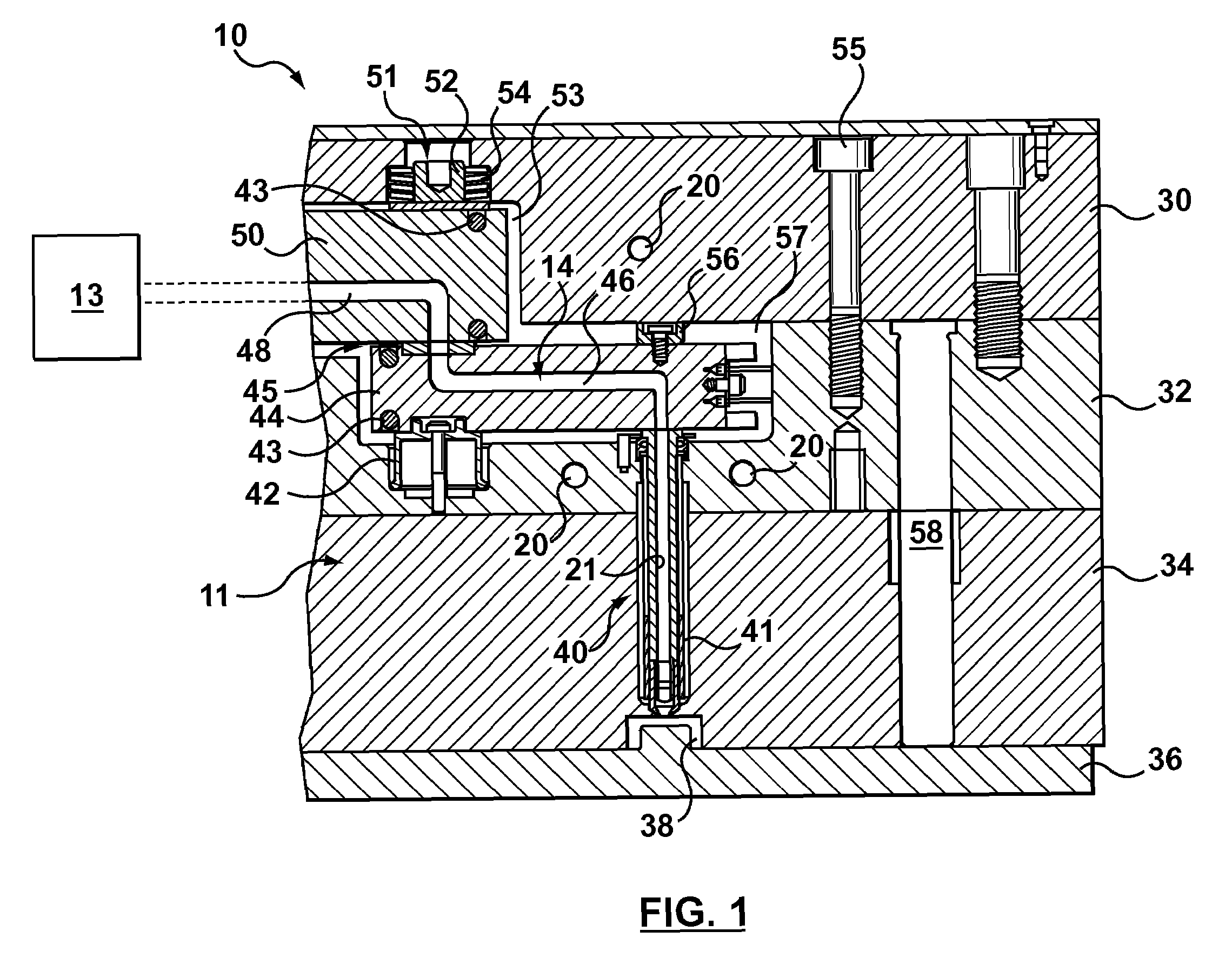
[0058]Generally, a composite material component for an injection molding assembly 10 is provided herein. The component includes a first portion formed of a precipitation hardened, high thermal conductivity material and a second portion formed of a precipitation hardened, high strength material, and the high thermal conductivity material and the high strength material are unitized or integrally joined together, e.g., by welding or other methods further described below. The thermal conductivity of the high thermal conductivity material is greater than the thermal conduct...


PUM

PropertyMeasurementUnit
Temperatureaaaaaaaaaa

Abstract

A composite nozzle tip for an injection molding assembly includes a body, having a bore extending therethrough, adapted for connection to the injection molding assembly. The body is formed of a precipitation hardened, high thermal conductivity material and a precipitation hardened, high strength material, which are integrally joined together to form the body. The thermal conductivity of the high thermal conductivity material is greater than the thermal conductivity of the high strength material, and the strength of the high strength material is greater than the strength of the high thermal conductivity material. The high thermal conductivity material and the high strength material can be precipitation hardened together under the same precipitation hardening conditions to achieve increases in the value of at least one strength aspect of the high thermal conductivity material and the value of at least one strength aspect of the high strength material, relative to their respective unhardened conditions.

Description

TECHNICAL FIELD[0001]The invention relates, generally, to injection molding systems, and more particularly, but not exclusively, to hot runner components and injection molding systems comprising such components, particularly nozzle assemblies and nozzle tips therefor.BACKGROUND OF THE INVENTION[0002]The state of the art includes various nozzles and tips for hot runner injection molding systems. Hot-runner nozzles are typically either a valve-gate style or a hot-tip style. In the valve-gate style, a separate stem moves inside the nozzle and tip acting as a valve to selectively start and stop the flow of resin through the nozzle. In the hot-tip style, a small gate area at the end of the tip freezes off to thereby stop the flow of resin through the nozzle.[0003]An injection molding system using a hot-tip style nozzle typically has a cooled mold with a small circular gate opening in which the tip of the nozzle is inserted. The tip is typically conical with a tapered point or other suita...

Claims


Application Information

Patent Timeline
IPC IPC(8): B29C45/20
CPCB29C45/278B29C2045/2783C22C9/06B29C2045/2787C21D9/00B29C2045/2785
Inventor BOUTI, ABDESLAM
Owner HUSKY INJECTION MOLDING SYST LTD
Learn More