Apparatus and method for implantation of a bifurcated endovascular prosthesis

a technology of endovascular prosthesis and applicator, which is applied in the field of applicator and method for implantation of bifurcated endovascular prosthesis, can solve the problems of consuming and unpredictable requirements, and achieve the effect of precise graft positioning, short and simple process, and revealing novelty and utility of the disclosed devi

Inactive Publication Date: 2008-08-28
SAEED MOHSIN
View PDF4 Cites 66 Cited by
  • Summary
  • Abstract
  • Description
  • Claims
  • Application Information

AI Technical Summary

Benefits of technology

[0018]An additional object of this invention is the provision of such a prosthesis which may be assembled from multiple components with ease and in a much reduced duration from a conventionally available device.
[0049]As those skilled in the art will realize, other means to releasably engage the secondary catheter guide wire to the escort catheter extending exposed from the first delivery catheter might be employed, and all as would occur to those skilled in the art are anticipated. However, because of the confined working environment, the compactness and ease of operation of the snare, the ability to provide memorized shapes to the snare, and the positive releasable mechanical engagement thereon, the current preferred mode of the device employs the snare to capture the secondary catheter for placement of a third guide wire in the contralateral cuff.

Problems solved by technology

As previously mentioned, this is encumbered by several factors, notably the small size of the target within a large aneurysm cavity, variably complex angles of approach imposed by iliac artery orientation relative to the axis of the aorta, and possible interference from the deployed long leg of the graft when a crossed-leg deployment is chosen.
Firstly, the time-consuming and unpredictable requirement of current art to maneuver a direct wire passage from the second iliac artery into the cuff after deployment of the device is eliminated.

Method used


Image

  • Apparatus and method for implantation of a bifurcated endovascular prosthesis
  • Apparatus and method for implantation of a bifurcated endovascular prosthesis
  • Apparatus and method for implantation of a bifurcated endovascular prosthesis

Examples


Embodiment Construction

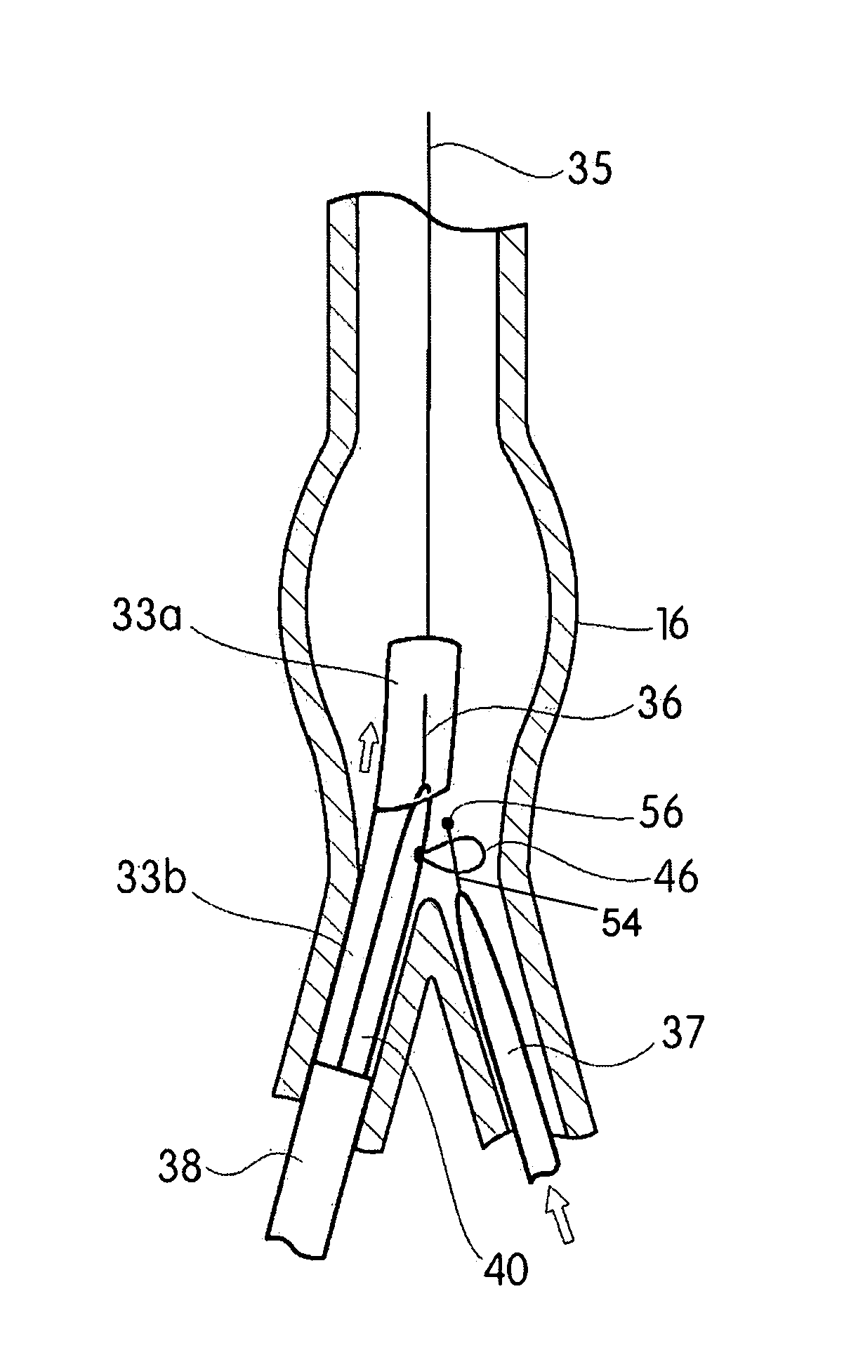
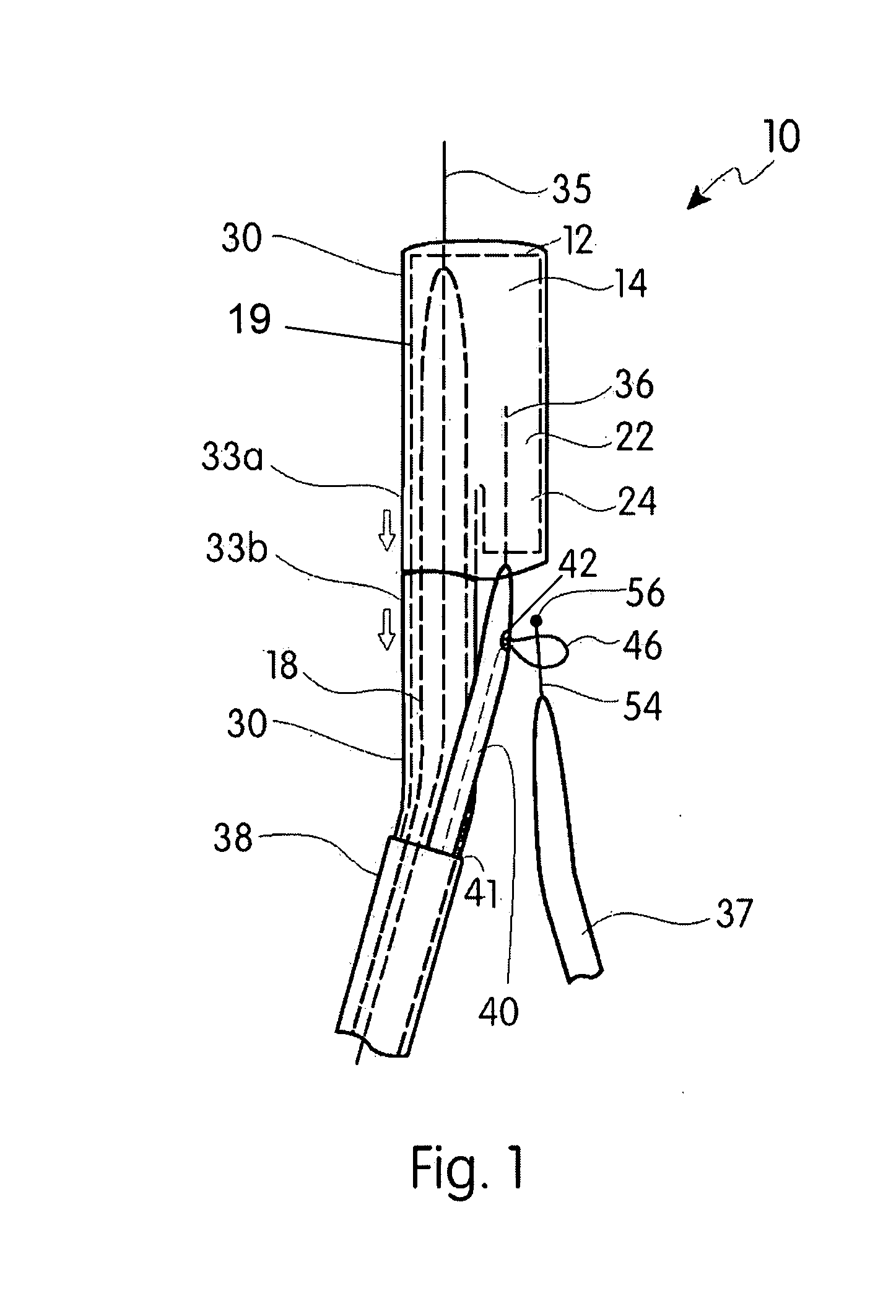
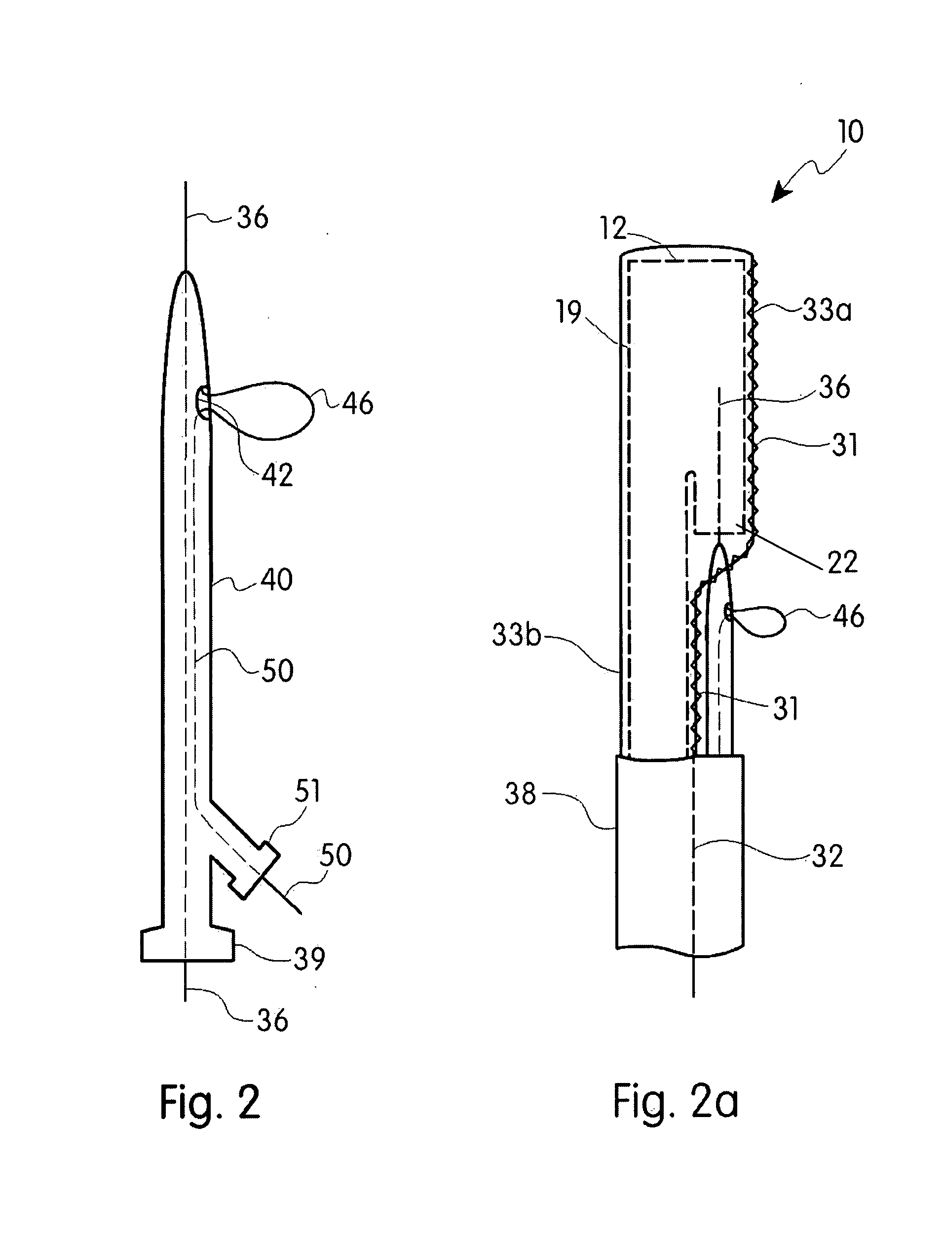
[0063]Referring now to the drawings in FIGS. 1-10, wherein similar parts are identified by like reference numerals, the device 10 is depicted in FIG. 1 which illustrates the components of the bifurcating prosthesis 12 engaged to the distal end of a delivery catheter 38. A trunk portion 14 is shown having a diameter adapted to engage within the walls of the aorta 16 shown in FIGS. 4-6. The trunk portion 14 is in communication with two smaller conduits extending from a lower end of the trunk 14, communicating with the larger open aperture at the upper end of the trunk 14. An ipsilateral or first leg 18 shown in FIG. 1 and FIGS. 4-10, has a diameter and a length adapted to extend into an engaged position communicating between the trunk 14 and one of the iliac arteries. The other shorter conduit shown in FIGS. 1 and 2a, is a cuff 22 portion extending from the lower end of the trunk 14 portion. As shown in other figures such as FIG. 10, the distal end 24 of the cuff 22 is adapted for eng...


PUM


Abstract

A bifurcated stent graft for animal or human implantation and method of delivery thereof. The device stent graft employs a first component having an axial passage communicating with the axial cavities of a second leg and longer first leg. A separate leg extension is engageable to the second leg. A first catheter engages the first component for translation to the implantation site and a second catheter engaged with the first is provided with a prepositioned guide wire inside the second leg which may be employed to easily position a guide wire for engagement of the second leg with the leg extension.

Description

[0001]This application claims priority from U.S. Provisional Patent Application Ser. No. 60 / 903,253 filed Feb. 22, 2007. The disclosed device relates to an endovascular prosthesis and implantation method therefor. More particularly it relates to a device and method for implantation of a bifurcated endoprosthesis for repair of infrarenal abdominal aortic aneurysms commonly known to those skilled in the art as AAA's.FIELD OF THE INVENTIONBackground of the Invention[0002]An aneurysm is a type of disease that affects the arteries and is manifested by a localized widening or enlargement of an artery compared to its normal size. Because of the potential of rupture of the artery in question, any aneurysm is a serious health problem and risk to a patient. When a blood vessel with an aneurysm ruptures, life-threatening bleeding generally is the result. Even prior to such an occurrence, aneurysms can also cause pain from pressure on nearby organs or nerves and on occasion, debris within the a...

Claims


Application Information

Patent Timeline
Patent Type & Authority Applications(United States)
IPC IPC(8): A61F2/06
CPCA61F2/07A61F2220/0075A61F2002/067A61F2/954
Inventor SAEED, MOHSIN
Owner SAEED MOHSIN
Why Eureka
Try Eureka