Vertical-position welding method

a welding method and vertical positioning technology, applied in the direction of welding/cutting media/materials, welding apparatus, manufacturing tools, etc., can solve the problems of substantial increase in costs, mechanical strength, and weld deterioration, so as to reduce costs, reduce costs, and achieve efficient and high-quality welding

Inactive Publication Date: 2008-09-04
IHI CORP +1
View PDF5 Cites 9 Cited by
  • Summary
  • Abstract
  • Description
  • Claims
  • Application Information

AI Technical Summary

Benefits of technology

[0012]The present invention was made to solve the above problems, and an object thereof is to provide a vertical-position welding method which can be applied to thick steel plates while restraining increase in costs, which requires only small heat input, thereby ensuring high mechanical strength, and which thus enables efficient and high-quality welding.
[0013]To achieve the object, the present invention provides a vertical-position welding method for carrying out arc welding by using an arc welding unit with a constant voltage characteristic. The vertical-position welding method comprises the steps of: setting up a pair of thick steel plates side by side such that an I groove with a predetermined narrow gap is formed between mutually facing edges of the thick steel plates; positioning a welding torch of the arc welding unit for feeding a welding wire such that only the welding wire projecting from the welding torch is inserted into the I groove obliquely from above with respect to a thickness direction of the thick steel plates; moving the welding torch up and down along the thick steel plates and reciprocating a distal end of the welding wire in the thickness direction of the thick steel plates by varying a wire feed rate and also increasing and decreasing a length of extension of the welding wire from the welding torch such that a welding current remains at a target value, to deposit metal inside the I groove; and controlling position of the distal end of the welding wire to an appropriate position in accordance with a moving direction of the welding torch when the distal end of the welding wire is reciprocated in the thickness direction of the thick steel plates.
[0014]With the vertical-position welding method of the present invention, the gap of the I groove can be narrowed; hence the required heat input can be reduced to a significantly low level despite the large plate thickness, compared with the conventional electrogas arc welding method in which welding is completed by one pass in the thickness direction of the plates. Consequently, it is unnecessary to use special steel products prepared specially for large heat-input welding, thus reducing costs. Also, fluctuation of the welding current from the target value is prevented to restrain variation in arc length, and accordingly, stable and high-quality welding can be efficiently performed while at the same time ensuring mechanical strength equivalent to that achieved by the conventional electrogas arc welding, whereby fracture toughness especially at low temperatures can be remarkably improved.

Problems solved by technology

Consequently, a wider region of the weld deteriorates in performance, giving rise to a problem that the weld fails to retain sufficiently high toughness, that is, mechanical strength.
However, the use of steel products specially prepared for large heat-input welding leads to substantial increase in costs and is not desirable.
Since the groove generally used in steel structures is a single V groove, however, the cross-sectional area of the groove is large, requiring much time for the construction of steel structures and significantly lowering the productivity.

Method used


Image

  • Vertical-position welding method
  • Vertical-position welding method
  • Vertical-position welding method

Examples


Embodiment Construction

[0022]An embodiment of the present invention will be described below with reference to the accompanying drawings.

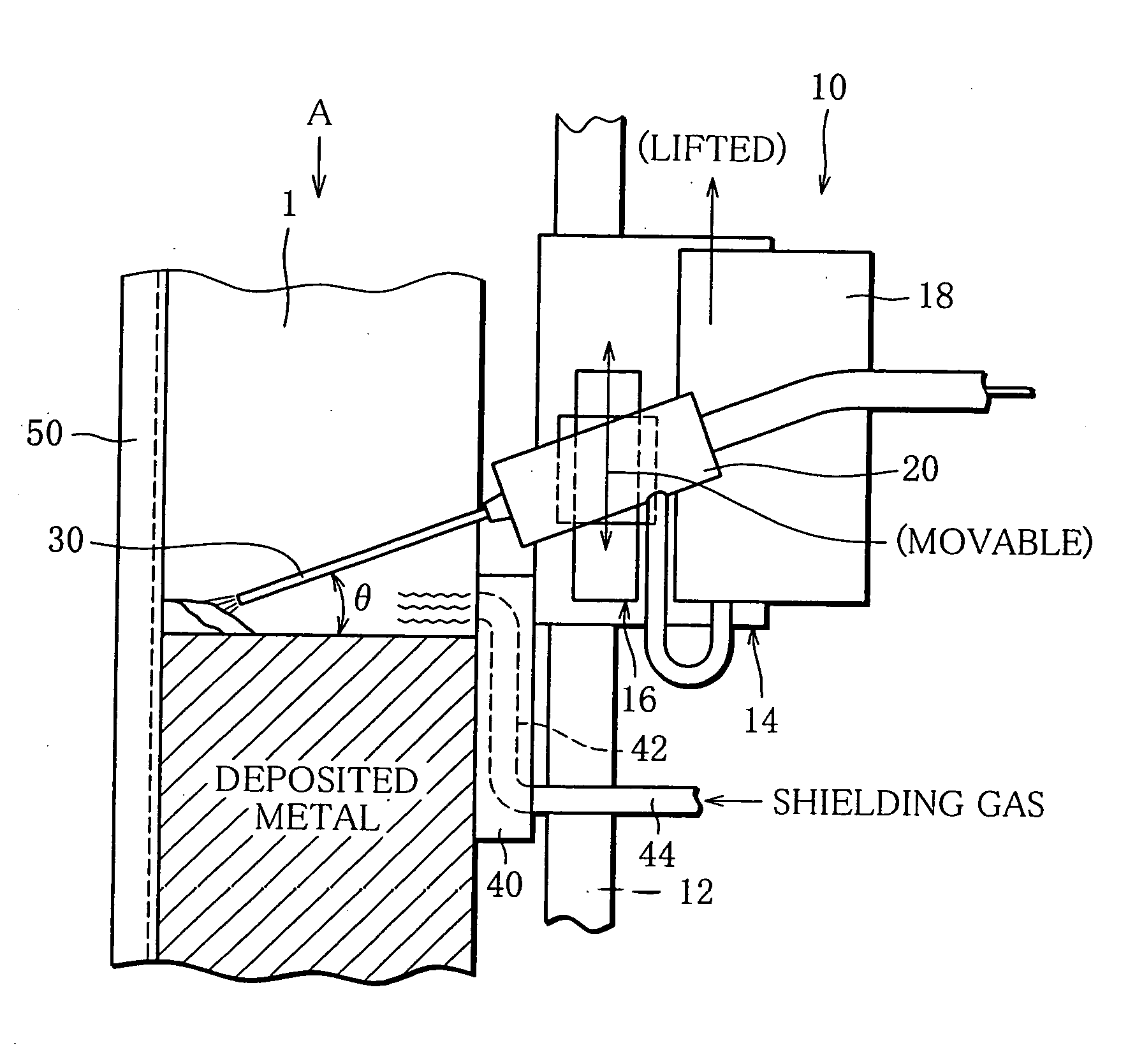
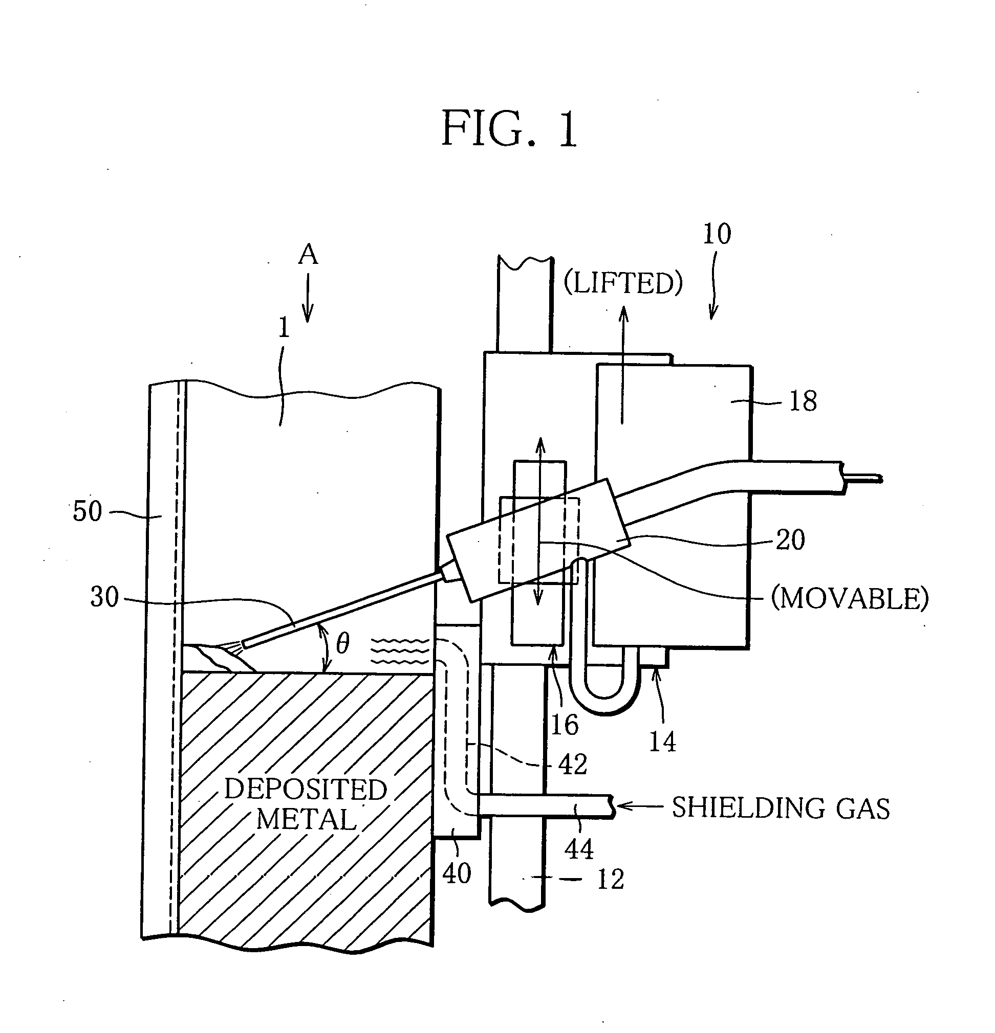
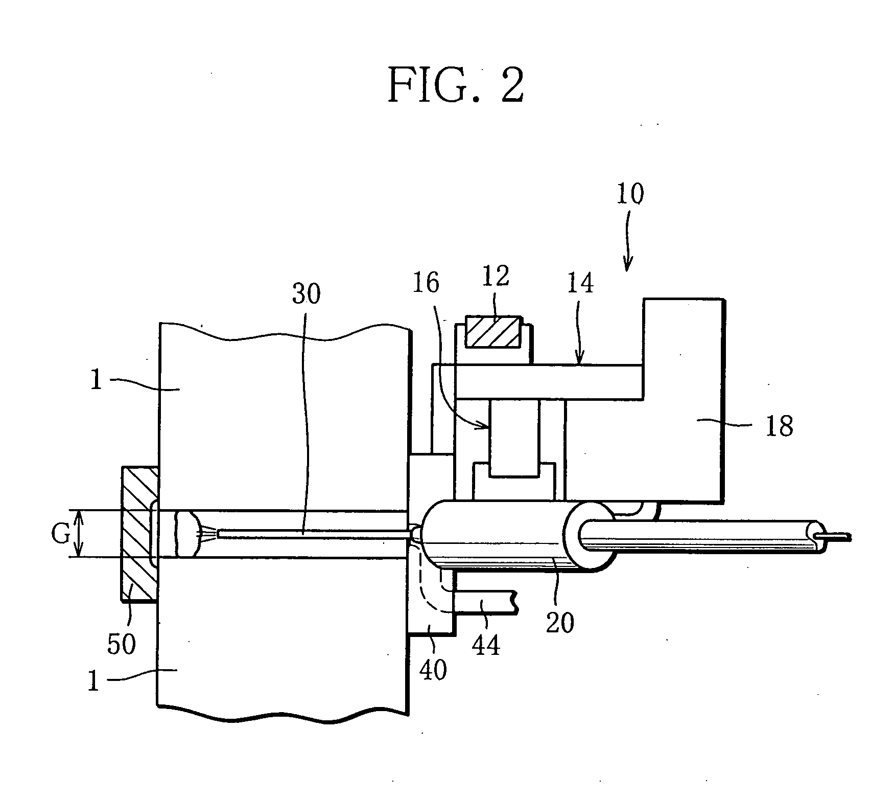
[0023]FIGS. 1 and 2 illustrate a state in which a pair of thick steel plates 1 are being welded together by an automatic arc welding unit 10 to which a vertical-position welding method of the present invention is applied. Specifically, the thick steel plates 1 are set up side by side such that an I groove with a gap G (predetermined narrow gap) is formed between the mutually facing edges thereof. The automatic welding unit 10 is provided with a welding torch 20 for feeding a welding wire 30. FIG. 1 shows the automatic welding unit 10 with its welding wire 30 inserted into the I groove between the thick steel plates 1, and deposited metal, in section, deposited inside the I groove. FIG. 2 shows the thick steel plates 1 and the automatic welding unit 10 as viewed from direction A in FIG. 1.

[0024]The thick steel plates 1 are plates of steel with a large thickness, like the o...


PUM

PropertyMeasurementUnit
thicknessaaaaaaaaaa
diameteraaaaaaaaaa
diameteraaaaaaaaaa

Abstract

A pair of thick steel plates are set up side by side such that an I groove with a narrow gap is formed between the facing edges of the plates, and a welding wire projecting from a welding torch of an arc welding unit with a constant voltage characteristic is inserted into the I groove obliquely from above with respect to the thickness direction of the plates. The welding torch is moved vertically while the distal end of the welding wire is caused to reciprocate inside the I groove in the thickness direction. At this time, the wire feed rate Vf is varied and also the extension L of the welding wire is increased or decreased so as to keep welding current Iw at a target value. Further, the wire feed rate Vf is subjected to incremental/decremental correction according to the moving direction of the torch.

Description

BACKGROUND OF THE INVENTION[0001]1. Field of the Invention[0002]The present invention relates to a vertical-position welding method, and more particularly, to a welding technique for welding butted edges of a pair of thick steel plates together in a vertical position.[0003]2. Description of the Related Art[0004]In shipbuilding sites or bridge construction sites, a vertical-position welding method is generally adopted in which butted edges of a pair of steel plates are welded together by a welder in a vertical position.[0005]As such vertical-position welding, an electrogas arc welding method has been known in which a pair of steel plates are welded together by a single welding pass in the width direction of the plates (see Unexamined Japanese Patent Publication No. H11-254131 and “Patent Maps Classified by Technical Fields” from the Japan Patent Office, Machinery 3: Arc Welding Technology, 1.3.6 Electrogas Arc Welding Method).[0006]Also, as common welding methods, multi-layer welding...

Claims


Application Information

Patent Timeline
Patent Type & Authority Applications(United States)
IPC IPC(8): B23K9/12
CPCB23K9/0213B23K9/133B23K9/126B23K9/12B23K9/00B23K9/02
Inventor NAKAMURA, TERUMIKIJI, NOBORUILJIMA, TORU
Owner IHI CORP
Why Eureka
Try Eureka