Low noise ac differential amplifier with reduced low corner frequency and current consumption

a differential amplifier and low noise technology, applied in the field of low noise differential ac amplifiers, can solve the problems of significant increase, small input capacitance, and increase of cpb>1/b> and cpb>2/b> between, and achieve the effect of restrainting any increase in current consumption and small input capacitan

Active Publication Date: 2008-09-04
STMICROELECTRONICS SRL
View PDF3 Cites 8 Cited by
  • Summary
  • Abstract
  • Description
  • Claims
  • Application Information

AI Technical Summary

Benefits of technology

[0009]An architecture of an AC differential amplifier that, while providing for a desirably small input capacitance, restrains any increase of current consumption to practically maintain it identical to that of the prior art amplifier of FIG. 2 has now been found.
[0010]This result may be attained by connecting to the current nodes (for leaving unchanged the input capacitance) of the transistors of the differential pair, that amplifies the input differential signal, a degeneration network that constitutes with the first differential pair a high frequency feedback loop. The degeneration network may include a capacitive network and a second differential pair of transistors of opposite type of conductivity to that of the first differential pair, and may be connected in series thereto, such that the same bias current of the first pair ...

Problems solved by technology

Unfortunately, in integrated circuits, when the size of the decoupling capacitors C is enlarged, the parasitic capacitances CP1 and CP2 between the plates of the integrated capacitors, and the silicon substrate on which the amplifier is integ...

Method used


Image

  • Low noise ac differential amplifier with reduced low corner frequency and current consumption
  • Low noise ac differential amplifier with reduced low corner frequency and current consumption
  • Low noise ac differential amplifier with reduced low corner frequency and current consumption

Examples


Embodiment Construction

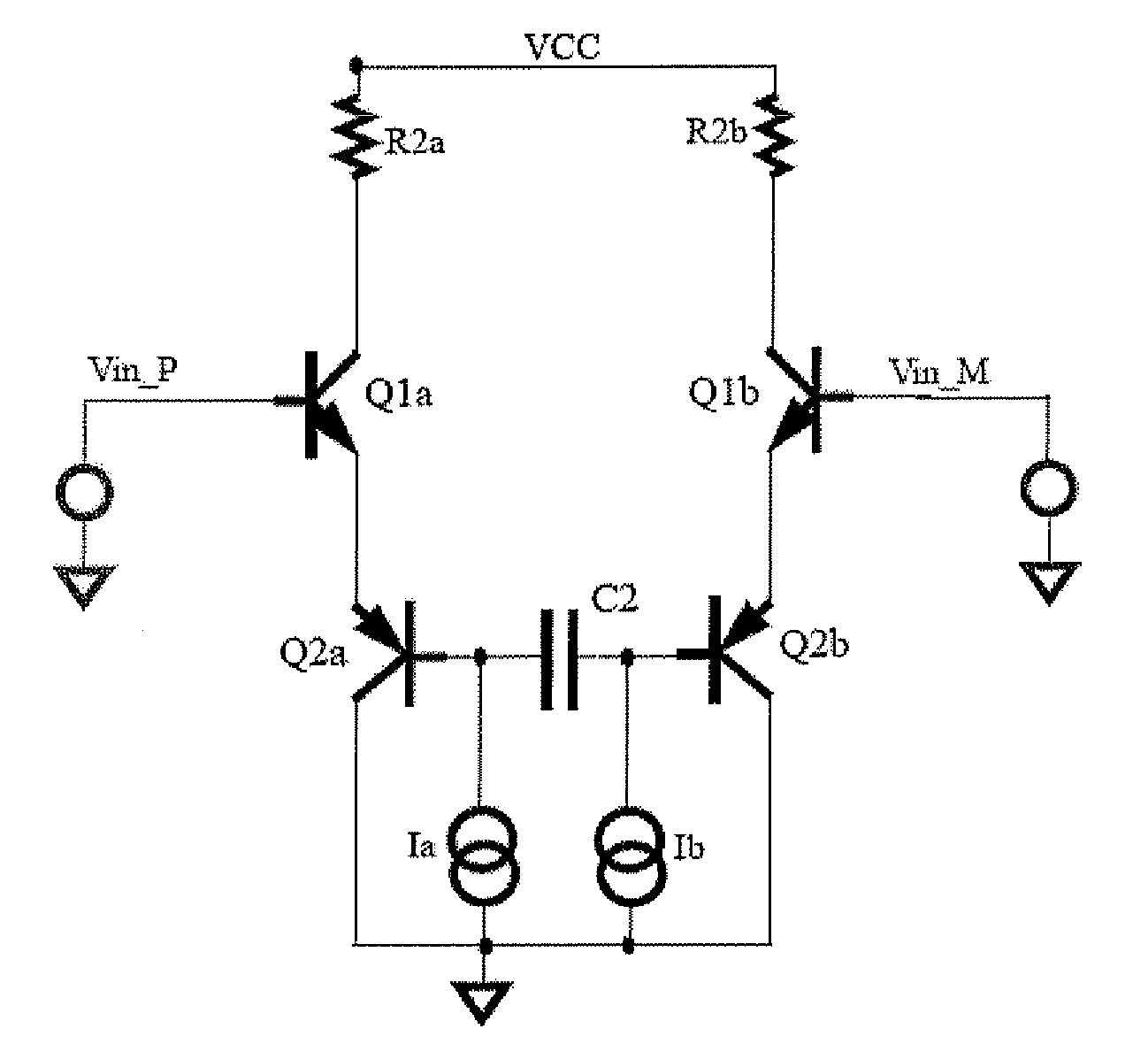
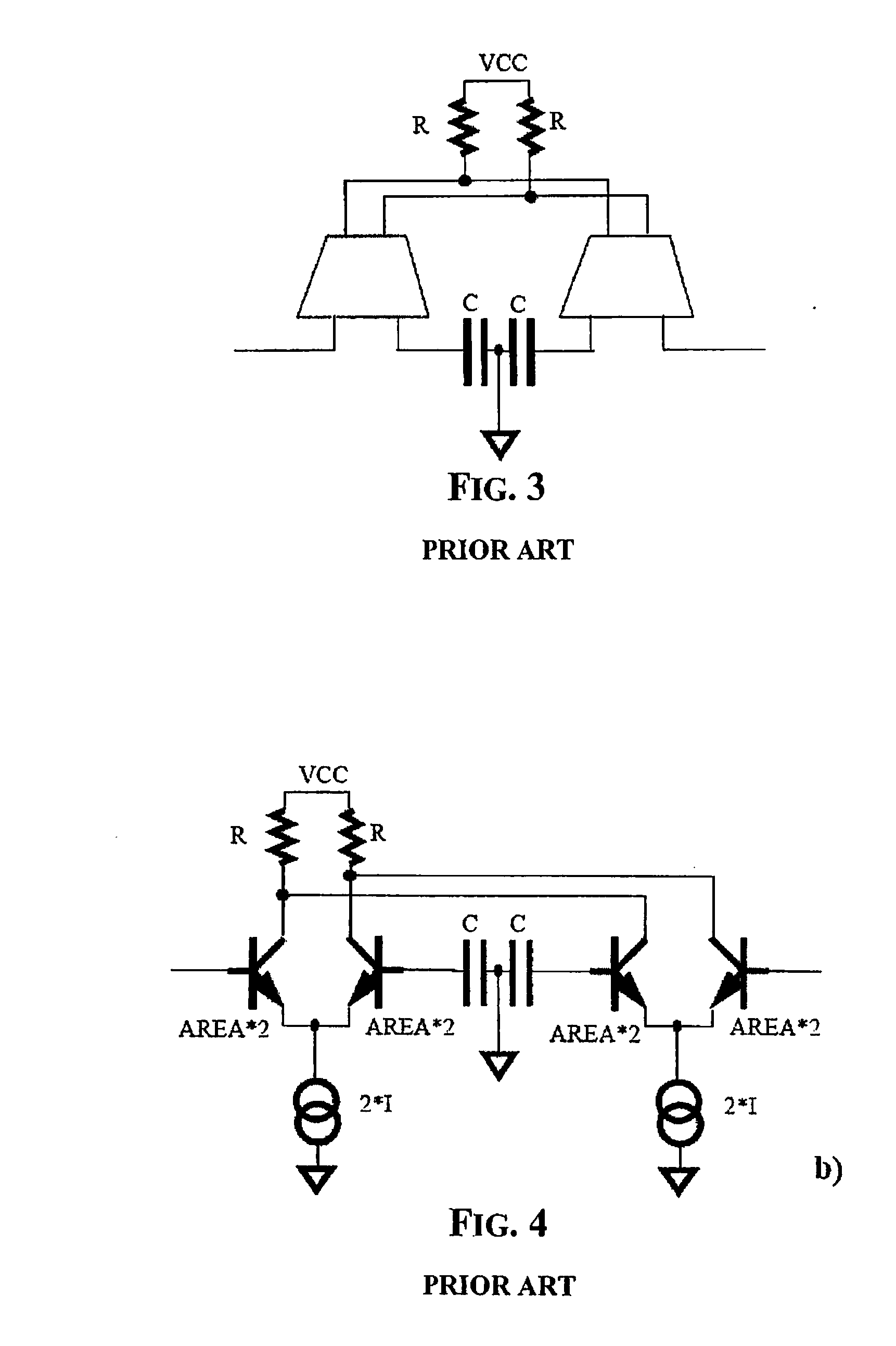
[0034]FIG. 5 depicts a first embodiment of the integrated AC amplifier with a small bias current. The proposed structure substantially includes a transconductance stage having a differential input pair of transistors Q1a and Q1b, that in the embodiment of FIG. 5 are two bipolar transistors NPN, connected to load resistors R2a and R2b, a second differential pair of transistors Q2a, Q2b, each biased by the same current that flows in the respective input transistor Q1a, Q1b. The transistors of the second differential pair Q2a, Q2b are biased by dedicated bias means or current generators Ia and Ib, as in the case shown in FIG. 4 are the current generators Ia and Ib.

[0035]Preferably, the currents Ia and Ib are fixed or controlled through a feedback loop for substantially nullifying the output offset voltage.

[0036]To better understand the functioning of the circuit of FIG. 5, let us refer to the single-ended circuit of FIG. 6a, that corresponds to a half of the integrated pre-amplifier. I...


PUM


Abstract

An integrated amplifier may include a transconductance stage including a differential pair of input transistors of a first type of conductivity, respective resistive loads coupled to said input transistors, and a first bias circuit coupled to the input transistors. The first bias circuit may include a second differential pair of bias transistors having first conduction terminals coupled in common and second conduction terminals coupled to respective conduction terminals of the input transistors. The first bias circuit may also include respective second bias circuits coupled to the bias transistors to enable the input transistors in a conduction state with the input transistors being biased by a same respective bias current that flows through the respective input transistors. The first bias circuit may also include a capacitive network coupled to the bias transistors to define with the input transistors a feedback loop.

Description

FIELD OF THE INVENTION[0001]This invention relates to AC amplifiers, and more particularly, to a low noise differential AC amplifier with reduced low corner frequency and reduced current consumption.BACKGROUND OF THE INVENTION[0002]In many applications it may be desirable to amplify an AC signal superimposed to a relatively large DC component. In these cases, an AC amplifier input with this signal through decoupling capacitors is commonly used. In particular, this happens in signal channels for recording data in hard disk drives (HDD).[0003]Two modes of recording data on a HDD are the so-called longitudinal recording and the vertical recording. As far as the AC amplifier is concerned, the main difference between these two techniques in that when using the longitudinal recording technique, a typical spectrum of an AC signal to be amplified, differs relevantly from the spectrum of the corresponding signal when using the vertical recording technique. As may be observed by comparing the...

Claims


Application Information

Patent Timeline
IPC IPC(8): H03F3/45
CPCH03F1/0205H03F1/08H03F3/4508H03F2203/45384H03F2203/45296H03F2203/45382H03F3/45085
Inventor BOLLATI, GIACOMINOALBASINI, GUIDO GABRIELE
Owner STMICROELECTRONICS SRL
Why Eureka
Try Eureka