
Silicon carbide semiconductor device integrating clamper circuit for clamping voltage

a silicon carbide semiconductor and clamping voltage technology, applied in semiconductor devices, diodes, electrical equipment, etc., can solve the problems of increasing packaging complications, occupying space, and damage to the gate oxide layer of the sic mosfet, so as to prevent device damage

Active Publication Date: 2022-01-11
SHANGHAI HESTIA POWER INC
View PDF8 Cites 0 Cited by
  • Summary
  • Abstract
  • Description
  • Claims
  • Application Information

AI Technical Summary

Benefits of technology

[0009]It is an object of the present invention to reduce the risk of damage of a conventional silicon carbide (SiC) semiconductor device during the switching process of the gate, wherein the damage is caused by a gate overvoltage likely generated due to a low specific on-resistance and a small input capacitance of the SiC semiconductor device.
[0010]It is another object of the present invention to improve the issue of having a lower tolerance against electrostatic discharge (ESD) occurring between the gate and the source of a conventional SiC semiconductor device, wherein the lower tolerance against ESD is caused by a low specific on-resistance and a small input capacitance of the SiC semiconductor device.
[0011]To achieve the objects above, the present invention provides a silicon carbide (SiC) semiconductor device integrating a clamper circuit for clamping voltage, thereby achieving the object of device protection, and effectively preventing device damage possibly caused by a positive overvoltage and a negative overvoltage between the gate and the source.
[0019]In one embodiment, the bidirectional voltage clamp can suppress a positive overvoltage and a negative overvoltage applied between the gate and the source.
[0023]The SiC semiconductor device integrating a MOSFET and a bidirectional voltage clamp of the present invention effectively prevents device damage caused by a positive overvoltage and a negative overvoltage between the gate and the source, further achieving the object of device protection.

Problems solved by technology

If an overvoltage of the gate exceeds the breakdown voltage of the gate oxide layer during the occurrence of ringing, the gate oxide layer of the SiC MOSFET can be damaged.
However, the additionally disposed Zener diode leads issues of increasing packaging complications, occupying space, decreasing reaction speed and inducing additional stray inductance; the integrally disposed polysilicon Zener diode causes instability issues such as a reduced breakdown voltage and an increased leakage current of the polysilicon Zener diode under a high temperature, and is unsuitable for a SiC MOSFET that may be used in high-temperature applications.
Hence, burden and loss of a gate driving circuit are increased.
Therefore, for example, U.S. Pat. No. 9,627,383 B2 protects the gate by integrating an additional lateral MOSFET; however, it also has issues of a more complicated structure and providing protection for only a negative overvoltage between the gate and the source.

Method used


Image

  • Silicon carbide semiconductor device integrating clamper circuit for clamping voltage
  • Silicon carbide semiconductor device integrating clamper circuit for clamping voltage
  • Silicon carbide semiconductor device integrating clamper circuit for clamping voltage

Examples


Embodiment Construction

[0032]Details and technical contents of the present invention are given with the accompanying drawings below.

[0033]The present invention provides a silicon carbide (SiC) semiconductor device integrating a clamper circuit for clamping voltage. Referring to FIG. 4 and FIG. 5, FIG. 4 shows a schematic diagram of a SiC semiconductor device integrating a clamper circuit for clamping voltage according to an embodiment of the present invention, and FIG. 5 shows a sectional schematic diagram of FIG. 4 along A-A. A SiC semiconductor device 1 integrating a clamper circuit for clamping voltage according to an embodiment of the present invention includes a SiC substrate 10, a metal-oxide-semiconductor field-effect transistor (MOSFET) 20 and a bidirectional voltage clamp 30. The MOSFET 20 can be a planar MOSFET or a trench MOSFET.

[0034]According to an embodiment of the present invention, the MOSFET 20 includes a SiC n-type drift layer 21, a gate 22, a source 23 and a drain 24. The SiC substrate ...


PUM

PropertyMeasurementUnit
breakdown voltageaaaaaaaaaa
voltageaaaaaaaaaa

Abstract

The present invention provides a silicon carbide (SiC) semiconductor device integrating a metal-oxide-semiconductor field-effect transistor (MOSFET) and a bidirectional voltage clamping circuit. An object of protecting a device is achieved by using the simple structure above, effectively preventing device damage that may be caused by a positive overvoltage and a negative overvoltage between a gate and a source.

Description

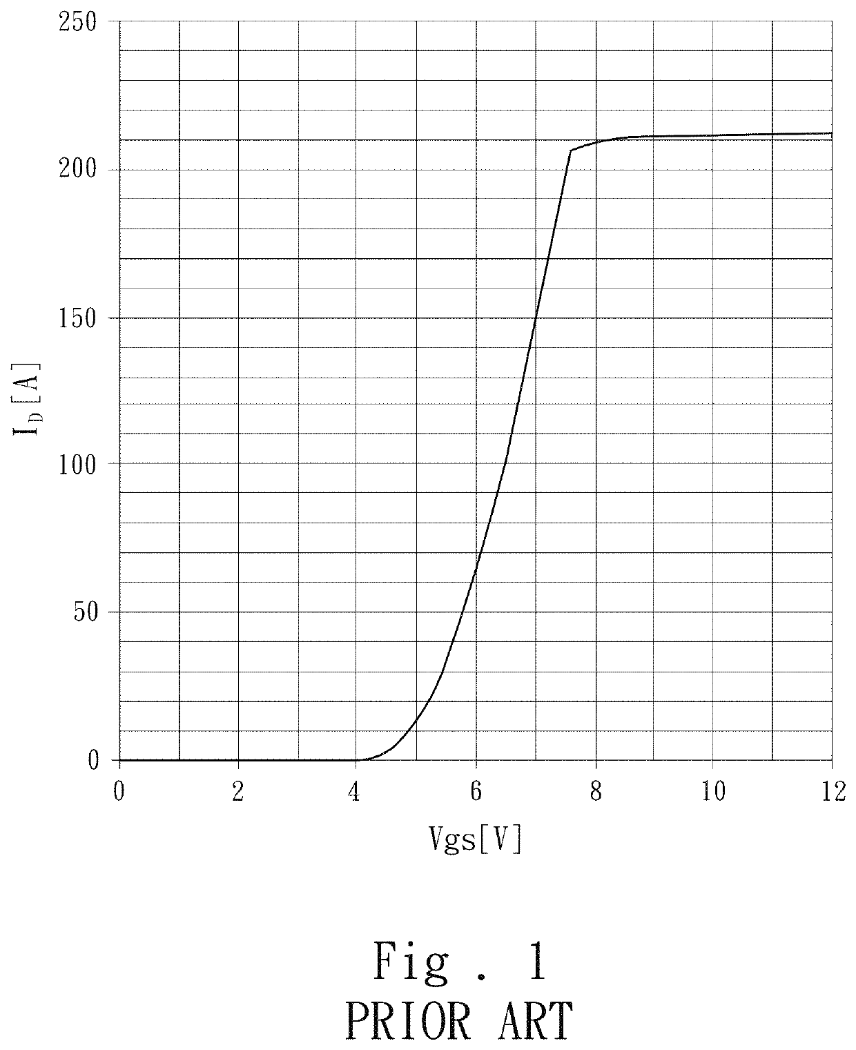
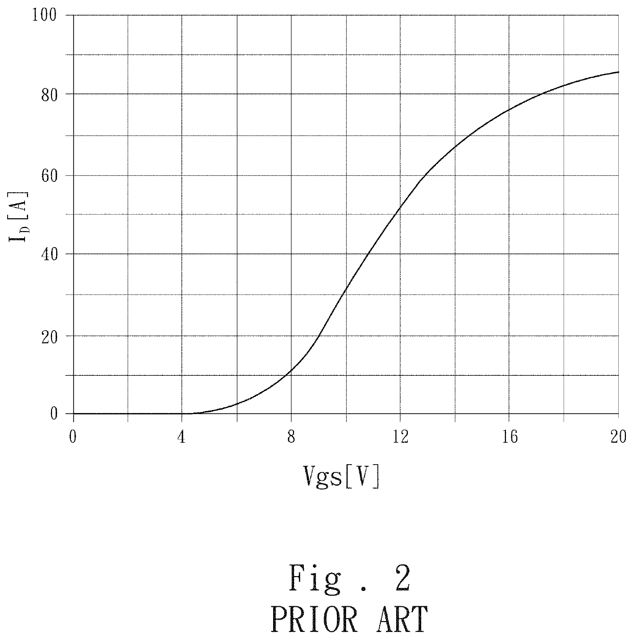
FIELD OF THE INVENTION[0001]The present invention relates to a semiconductor power device, and particularly to a silicon carbide (SiC) semiconductor device.BACKGROUND OF THE INVENTION[0002]Due to the presence of a wide energy gap of silicon carbide, given the same drain-to-source voltage (VDS) specification, a specific on-resistance (ron, sp=on resistance*active area) of a silicon carbide metal-oxide-semiconductor field-effect transistor (to be referred to as a SiC MOSFET hereafter) is far less than that of a silicon metal-oxide-semiconductor field-effect transistor (to be referred to as a Si MOSFET hereafter). By comparing transfer characteristics of a Si MOSFET and a SiC MOSFET, it is discovered that, the drain current (ID) of the Si MOSFET rises with the gate voltage (Vgs) and quickly reaches saturation (FIG. 1); however, the drain current (ID) of the SiC MOSFET still continuously rises with a rising of the gate voltage (Vgs) (FIG. 2).[0003]Therefore, a SiC MOSFET is usually oper...

Claims


Application Information

Patent Timeline
Patent Type & Authority Patents(United States)
IPC IPC(8): H01L29/78H01L29/73H01L29/06H01L29/16
CPCH01L29/7803H01L29/0615H01L29/1608H01L29/7302H01L27/088H01L29/7808H01L27/0255
Inventor YEN, CHENG-TYNGHUNG, CHIEN-CHUNGHSU, FU-JENCHU, KUO-TING
Owner SHANGHAI HESTIA POWER INC
Learn More