Broad Band Mechanical Phase Shifter

a mechanical phase shifter and broad band technology, applied in waveguide devices, electrical devices, waveguides, etc., can solve the problems of phase shifter no longer working properly, limited use of striplines, and variable characteristic impedance of dielectric movement, so as to improve the range of pointing angle and reduce the effect of vibration, preventing vibration, and reducing the effect of pointing angl

Inactive Publication Date: 2008-09-04
RADIACION Y MICROONDAS
View PDF99 Cites 14 Cited by
  • Summary
  • Abstract
  • Description
  • Claims
  • Application Information

AI Technical Summary

Benefits of technology

[0005]This invention characterises the special configuration and design of the phase shifter, which allows obtaining a greater range of variation of the pointing angle of the assembly of radiating elements with respect to the state of the art, such that the coverage area can be modified.
[0006]Another characteristic of the phase shifter object of the invention is that its configuration and design prevents vibrations, sag and the lack of rigidity of the striplines used in phase shifters in the state of the art.

Problems solved by technology

One of the drawbacks of such a system is the variation in the characteristic impedance as the dielectric moves.
On one hand, if the striplines exceed a certain length, resonances appear due to excitation of higher modes, so that after this length the phase shifter no longer works properly.
This is, the limitation in the use of striplines after a certain length limits the range of variation of the pointing angle.
Another disadvantage of the striplines of said invention is their low mechanical rigidity, more so if the dielectric used is air, as said striplines lack any support to minimise vibrations or sagging.
This is an important factor, as vibrations, sagging or deformations of striplines can lead to losses or variations in the voltage standing wave ratio (VSWR).
Another drawback of current mechanical phase shifters is the impossibility of actuating several common feeds of different phase shifters, requiring control by a single actuator.
In addition, the matching of the input signal transmission line to a specific impedance is performed externally to the phase shifter with cable lengths of different characteristic impedance and / or with impedance matching circuits, which increases the cost and complexity of the assembly.

Method used


Image

  • Broad Band Mechanical Phase Shifter
  • Broad Band Mechanical Phase Shifter
  • Broad Band Mechanical Phase Shifter

Examples


Embodiment Construction

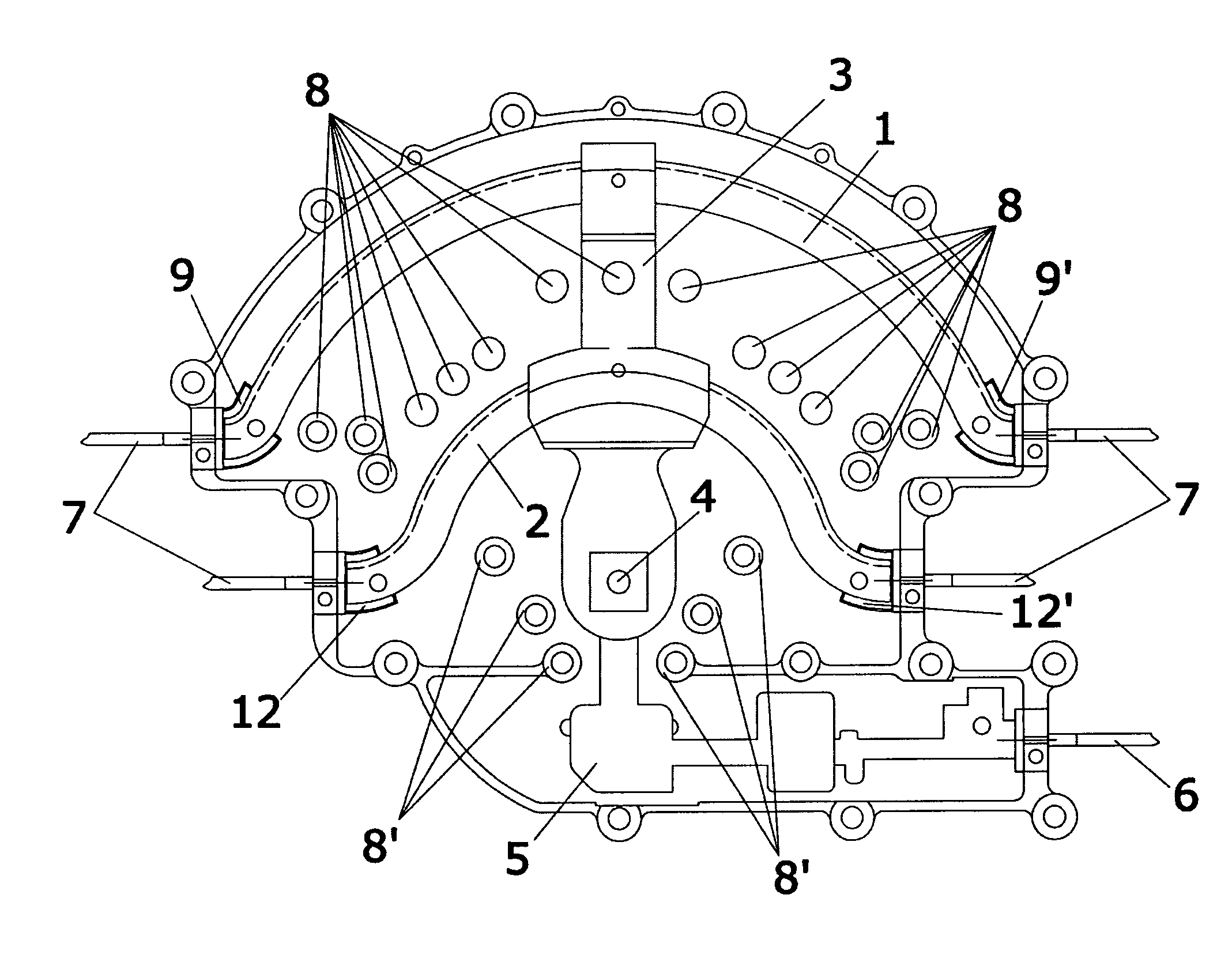
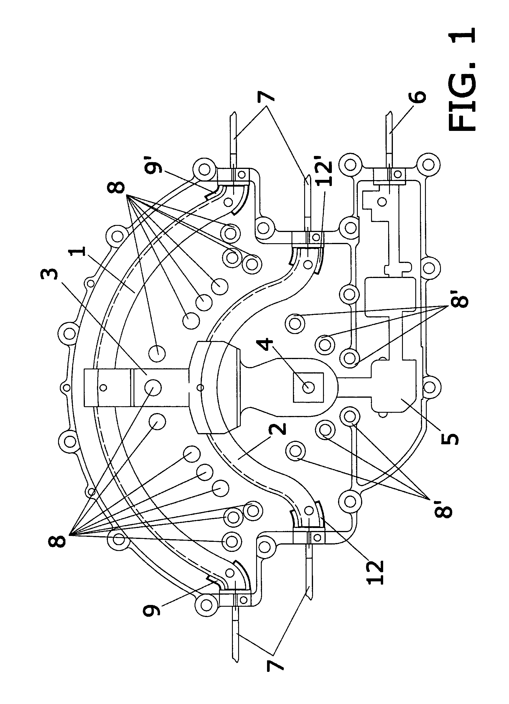
[0025]The mechanical phase shifter of the invention provides various pointing angles to an antenna formed by a group of radiating elements. The various pointing angles are the resulting of feeding an electrical high-frequency signal to the various radiating elements conforming the array with a different phase at each one.

[0026]For this purpose, the phase shifter is provided with one or more L-lines. If there are several L-lines they will be arranged concentrically. In addition, it has a common feed element that runs above the L-lines.

[0027]The common feed element revolves about a central shaft on one of its ends, located near the centre of curvature of the L-lines.

[0028]As the common feed element runs along the L-lines, the relative differences of the signal phase at the ends of the L-lines are modified.

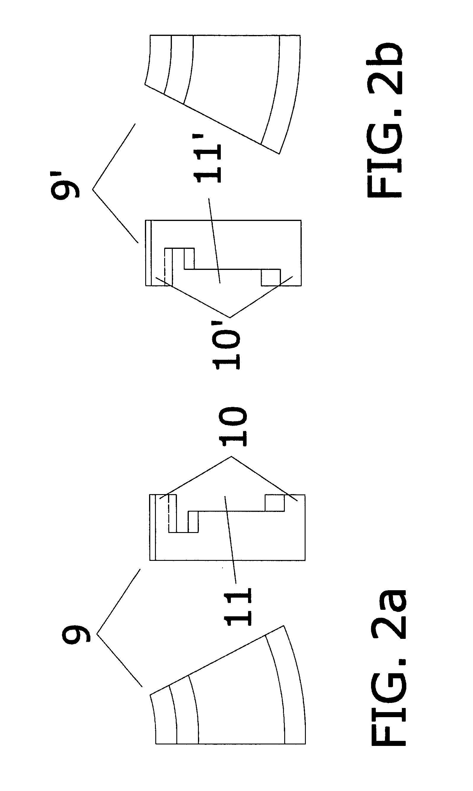
[0029]As the L-lines have a greater length than the striplines of state-of-the-art phase shifters and are supported at their ends and at the recess defined in the common feed element...


PUM


Abstract

Mechanical phase shifter which from an external feed signal obtains several signals out of phase with each other, each one of which is applied to an antenna of an array, so that the result of the interference of the radiated fields provides a radiation pattern. The object of the invention is to obtain a greater range of pointing angles, achieved by protrusions or screws that act as capacitors or short-circuits that allow suppressing the higher modes generated in the phase shifter, as well as preventing part of the mutual coupling between the phase shifter L-lines. In addition, due to the greater length of the L-lines, these are reinforced by a protrusion perpendicular to the greater length of the line located on the outer edge of each L-line, and in addition they are provided with supporting means for the L-lines which minimise the vibrations, sag and deformations. The L-lines also increase the frequency at which higher modes appear.

Description

OBJECT OF THE INVENTION[0001]The object of the present invention is a broad band mechanical phase shifter. One of the applications of phase shifters is to provide an electromechanical dynamic control of the beam radiated by an antenna array.[0002]An antenna array consists of an assembly of N antennae, identical or otherwise, which radiate or receive simultaneously. The radiation pattern of the assembly is obtained as the interference of the fields radiated by each antenna, while for reception the signal is a linear combination of the signals captured by each antenna.[0003]Phase shifters allow obtaining different pointing angles by feeding each antenna of the assembly with an electrical high-frequency signal with a different phase for each antenna.[0004]The physical principle used is the electrical delay produced in the transmission lines to adjust the signal phase at the various feed points of the radiating elements of the array.[0005]This invention characterises the special configu...

Claims


Application Information

Patent Timeline
Patent Type & Authority Applications(United States)
IPC IPC(8): H01P1/18
CPCH01P1/182H01P3/087H01P1/184
Inventor ARDERIU, RAMON GUIXA
Owner RADIACION Y MICROONDAS
Why Eureka
Try Eureka