Astrometry and photometry with coronagraphs

a coronagraph and astrometry technology, applied in the direction of instruments, mirrors, structural/machine measurement, etc., can solve the problems of significant brighter and larger stars, distortions of star images, and significant difficulties in an exoplanet orbiting the star,

Active Publication Date: 2008-09-04
AMERICAN MUSEUM OF NATURAL HISTORY
View PDF5 Cites 5 Cited by
  • Summary
  • Abstract
  • Description
  • Claims
  • Application Information

AI Technical Summary

Benefits of technology

[0005]The present invention provides a new and improved method and device ...

Problems solved by technology

A difficulty encountered in the exoplanet study effort is the fact that the star is significantly brighter and larger in size than any exoplanet in orbit around the star.
Distortions of the star image further complicate exoplanet study.
However, due to inherent aberrations in the optics of a telescope, the image of the point source comprising the star, is spread over a finite area of a sensor receiving and recording the image from the optics of the telescope.
Thus, a bright star whose image is distorted by PSF, presents significant difficulties to an accurate and co...

Method used


Image

  • Astrometry and photometry with coronagraphs
  • Astrometry and photometry with coronagraphs
  • Astrometry and photometry with coronagraphs

Examples


Embodiment Construction

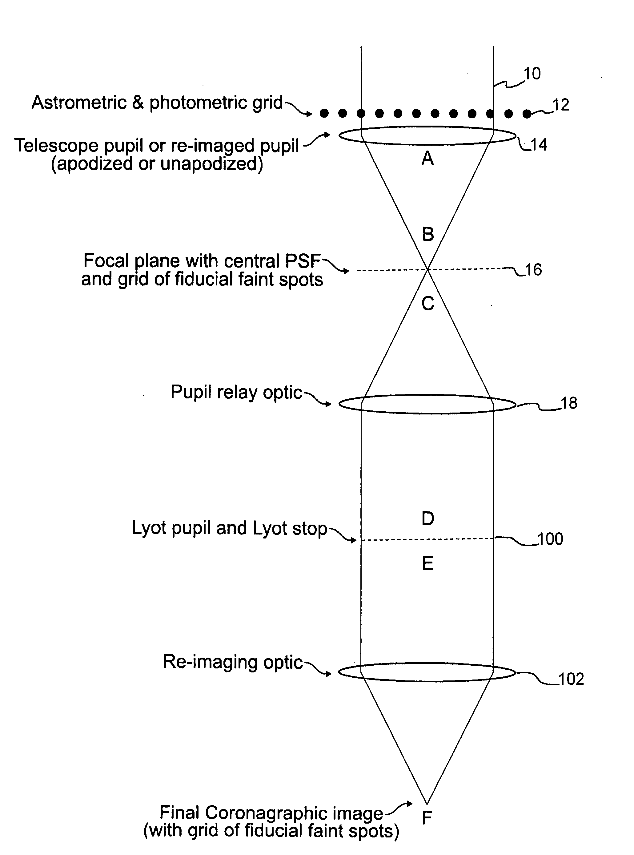
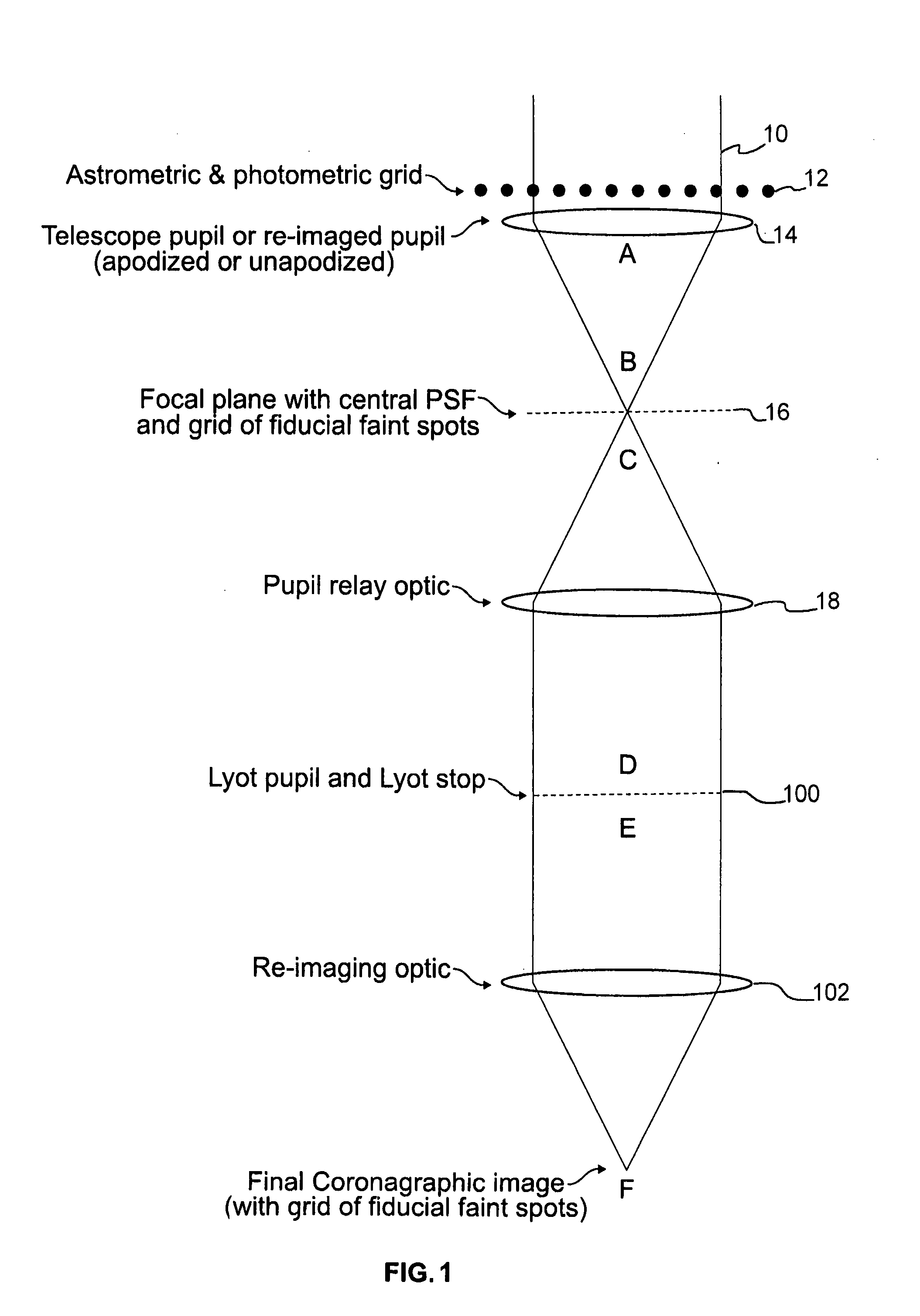
[0018]Referring now to the drawings, and initially to FIG. 1, there is shown a schematic diagram of a telescopic imaging device including a coronagraph device and a reticulate grid element according to an exemplary embodiment of the present invention. A beam of light 10 is propagated through a path within a telescope, through a reticulate grid element comprising a grid of wires 12, to a telescope pupil 14. The grid of wires 12 overlies the pupil 14 such that the beam of light 10 is transmitted through the wires of the grid 12 before transmission through the pupil 14. The pupil 14 is a lens arranged to focus the beam of light 10, as emitted from the pupil 14, at A, to a focal plane 16, at B. The image at the focal plane 16 has a central PSF, corresponding to, for example, a star being observed, and caused by inherent aberrations in the optics of the telescope, as described above.

[0019]Moreover, according to a feature of the present invention, the image at the focal plane 16 further i...


PUM


Abstract

In a first exemplary embodiment of the present invention, an optical device comprises a telescope, a coronagraph device coupled to the telescope and having a focal plane occulting mask to provide a coronagraphic image, and a reticulate grid element arranged in a light path propagated through the telescope, at a location relative to the coronagraphic image, to create controlled fiducial spots in the coronagraphic image.

Description

BACKGROUND OF THE INVENTION[0001]In modern astronomy, an important activity is the search for and study of exoplanets. An exoplanet is a planet in orbit around a star other than the sun. A difficulty encountered in the exoplanet study effort is the fact that the star is significantly brighter and larger in size than any exoplanet in orbit around the star. Distortions of the star image further complicate exoplanet study. For example, a point spread function (PSF) of an optical system is the irradiance distribution on a recorded image that results from a single point source in object space. A star in space is so far from earth, that it appears as a point to an earthbound telescope, or even to a telescope in orbit around the earth. However, due to inherent aberrations in the optics of a telescope, the image of the point source comprising the star, is spread over a finite area of a sensor receiving and recording the image from the optics of the telescope. Thus, a bright star whose image...

Claims


Application Information

Patent Timeline
IPC IPC(8): G02B5/08
CPCG02B5/003G02B23/12G02B23/00G02B5/18
Inventor SIVARAMAKRISHNAN, ANANDOPPENHEIMER, BEN R.
Owner AMERICAN MUSEUM OF NATURAL HISTORY
Why Eureka
Try Eureka