Compression connection for vertical IC packages

Inactive Publication Date: 2008-09-04
RPX CORP
View PDF26 Cites 1 Cited by
  • Summary
  • Abstract
  • Description
  • Claims
  • Application Information

AI Technical Summary

Benefits of technology

[0006]In accordance with a first aspect of the invention, springs (e.g., elastomers or metal leaf or coil springs) under co

Problems solved by technology

These solder joints have a reduced life due to high stresses created from the mismatch between the coefficient of thermal expansion of the substrate and the coeffic

Method used


Image

  • Compression connection for vertical IC packages
  • Compression connection for vertical IC packages

Examples


Example

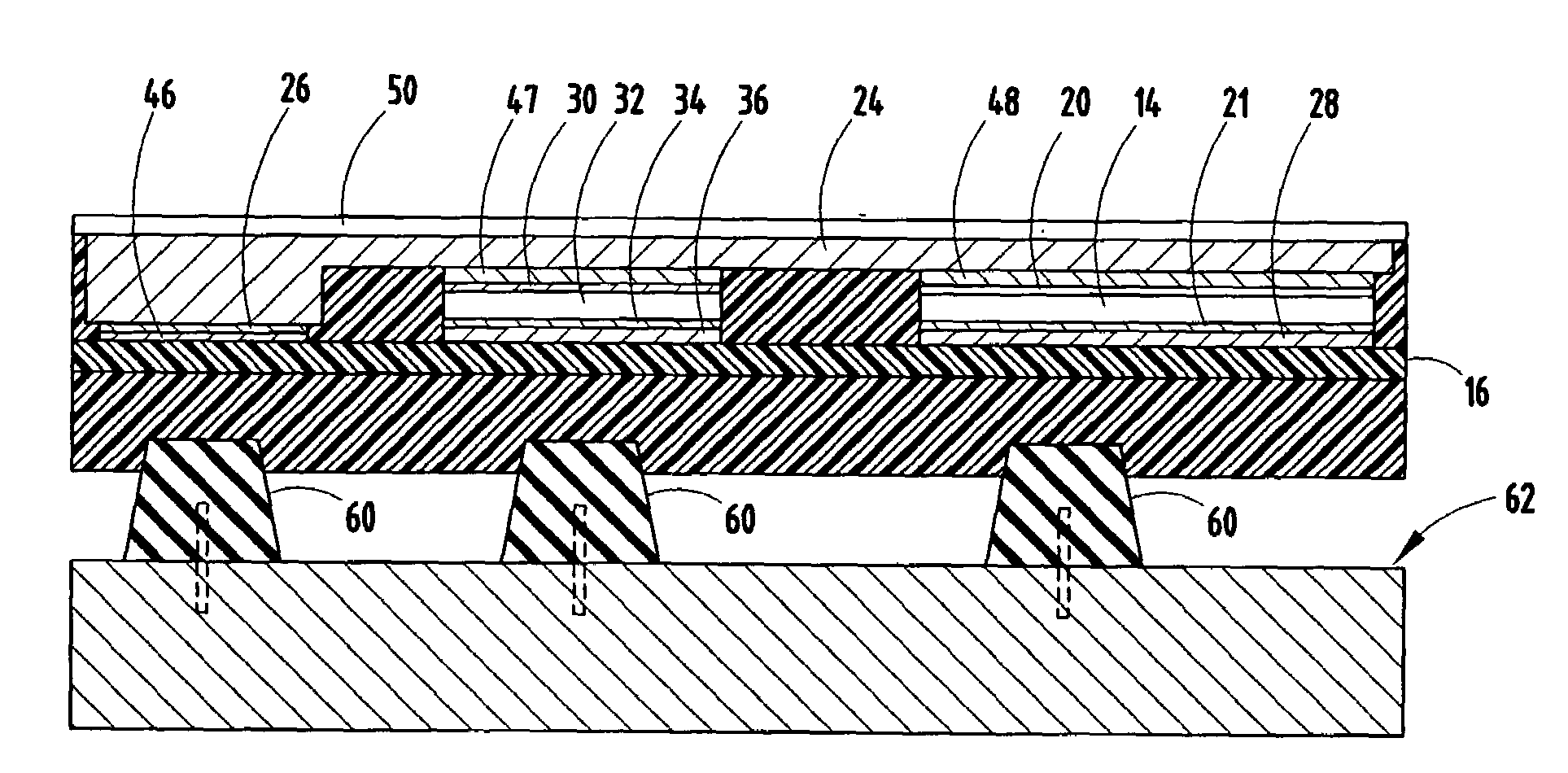
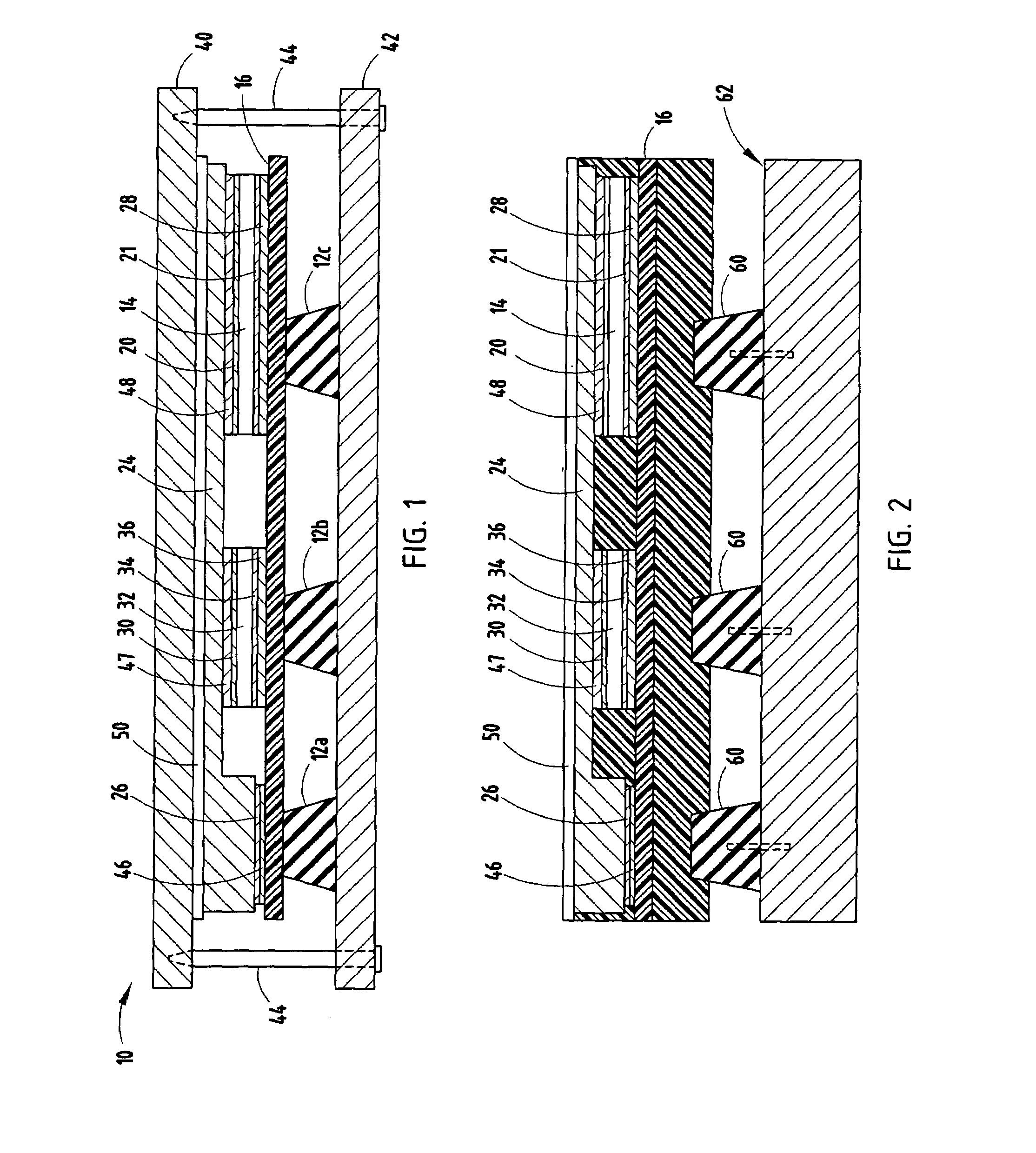
[0012]Shown in FIG. 1 is a vertical device integrated circuit package 10 utilizing springs 12a, 12b and 12c that are under compression to provide a claming force to ensure electrical contact of an integrated circuit device 14 (e.g., an IGBT) with a printed circuit board 16. Integrated circuit device 14 is a vertical device, more particularly, an IGBT, having metalized electrodes (electrical contacts) 20, 21 on opposite surfaces. An electrically conductive element 24 (e.g., copper strap) electrically connects electrical contact 20 of IGBT with an electrical contact 26 on printed circuit board 16, while the electrical contact 21 on the opposite side of IGBT 14 is electrically connected to a separate electrical contact 28 on printed circuit board 16. In the illustrated embodiment, a diode 32 is included in package 10. Diode 32 includes an electrical contact 30 electrically connected to conductive element 24 and a second electrical contact 34 on a surface opposite the surface on which e...


PUM


Abstract

An improved vertical integrated circuit device package that eliminates or reduces the need for wire bond connections and/or solder connections is provided. The package includes a vertical device having electrodes on opposite surfaces, and a compressed spring member that is used to establish compression electrical connections between the electrodes and corresponding electrically conductive elements.

Description

TECHNICAL FIELD [0001]The invention relates to integrated circuits (IC) packages, and more particularly to electrical connections for high current vertical device IC packages.BACKGROUND OF THE INVENTION [0002]Various types of circuit board components have been specifically developed for high current and high power applications, such as hybrid and electric vehicles. Such components often comprise a semiconductor device, such as a diode, thyristor, metal oxide semiconductor field effect transistor (MOSFET), isolated gate bipolar transistor (IGBT), resistors, etc., depending on the particular circuit and use desired. Vertical devices are typically formed in a semiconductor (e.g., silicon) die having metalized electrodes on its opposite surfaces, e.g., a MOSFET or IGBT with a drain / collector electrode on one surface and gate and source / emitter electrodes on its opposite surface. The die is mounted on a conductive pad for electrical contact with the drain / collector electrode, with connec...

Claims


Application Information

Patent Timeline
IPC IPC(8): H05K7/00
CPCH01L24/72H01L2924/1203H01L2924/1305H01L2924/1301H01L2924/1306H01L2924/10253H01L2924/01029H01L2224/06181H01L2224/05644H01L2924/13055H01L2924/13091H01L2924/14H01L2924/19043H05K7/2049H01L24/05H01L24/06H01L25/072H01L2924/00H01L2924/181
Inventor BRANDENBURG, SCOTT D.DEGENKOLB, THOMAS A.YEH, SHING
Owner RPX CORP
Why Eureka
Try Eureka