High pressure fuel pump control apparatus for an internal combustion engine

Inactive Publication Date: 2008-09-11
MITSUBISHI ELECTRIC CORP
View PDF4 Cites 46 Cited by
  • Summary
  • Abstract
  • Description
  • Claims
  • Application Information

AI Technical Summary

Benefits of technology

[0016]Accordingly, the present invention is intended to obviate the problems as referred to above, and has for its object to obtain a high pressure fuel pump control apparatus for an internal combustion engine which has a high pressure fuel pump of an engine driven type capable of pressure feeding a controlled amount of fuel by driving a fuel suction valve to close at predeter

Problems solved by technology

As a result, it is impossible to control the fuel suction valve to close on a fuel delivery stroke before the cylinder identification has been completed.
However, this rated delivery pressure is very low as compared with the target pressure (e.g., 7 MPa) in the accumulator in normal operation time, and hence it is difficult to achieve the injection of fuel that is able to obtain a good combustion state.
In addition, the valve closing timing of the fuel suction valve at engine starting becomes a probabilistic or rare operation, so the amount of delivery fuel varies each tim

Method used


Image

  • High pressure fuel pump control apparatus for an internal combustion engine
  • High pressure fuel pump control apparatus for an internal combustion engine
  • High pressure fuel pump control apparatus for an internal combustion engine

Examples


embodiment 1

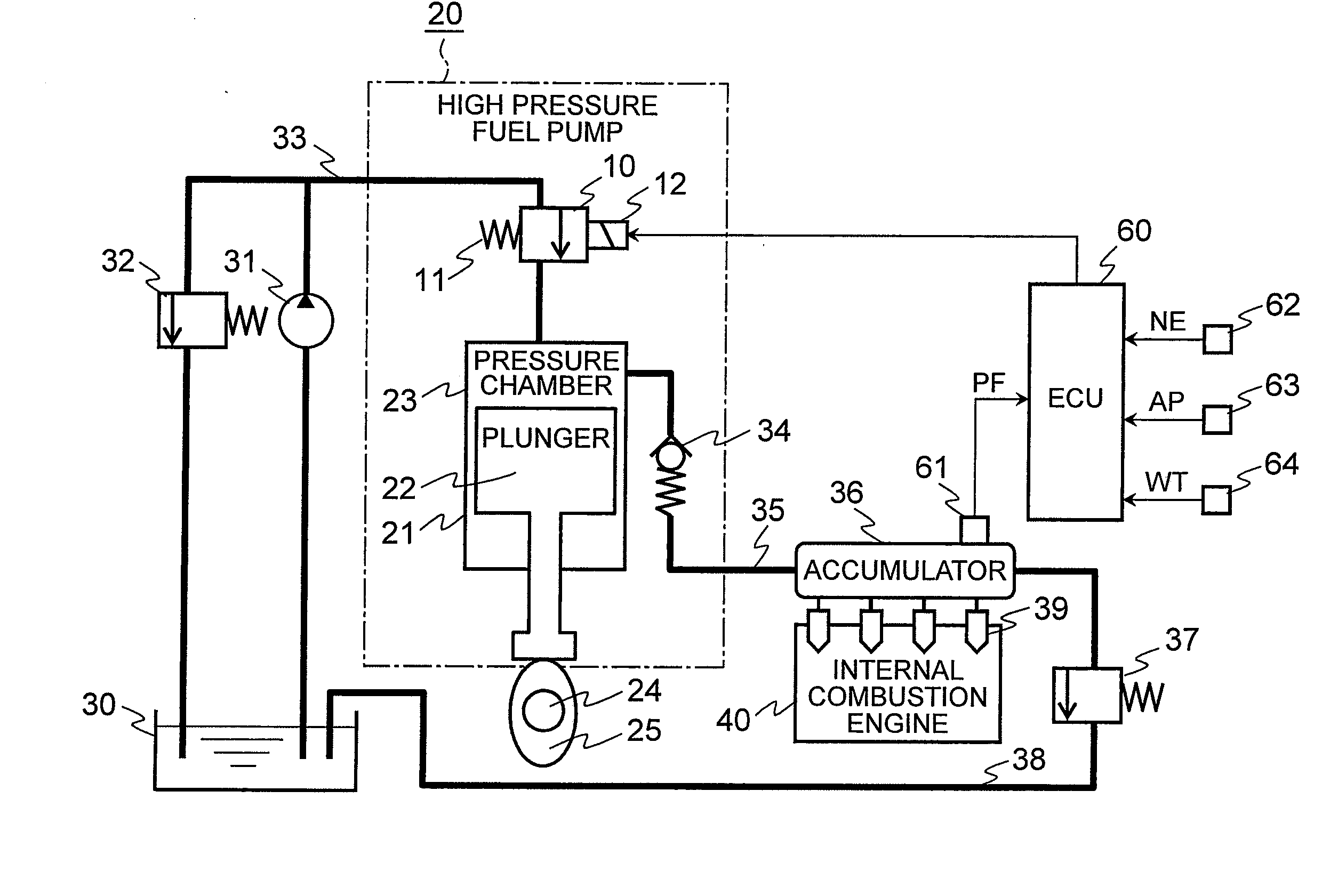
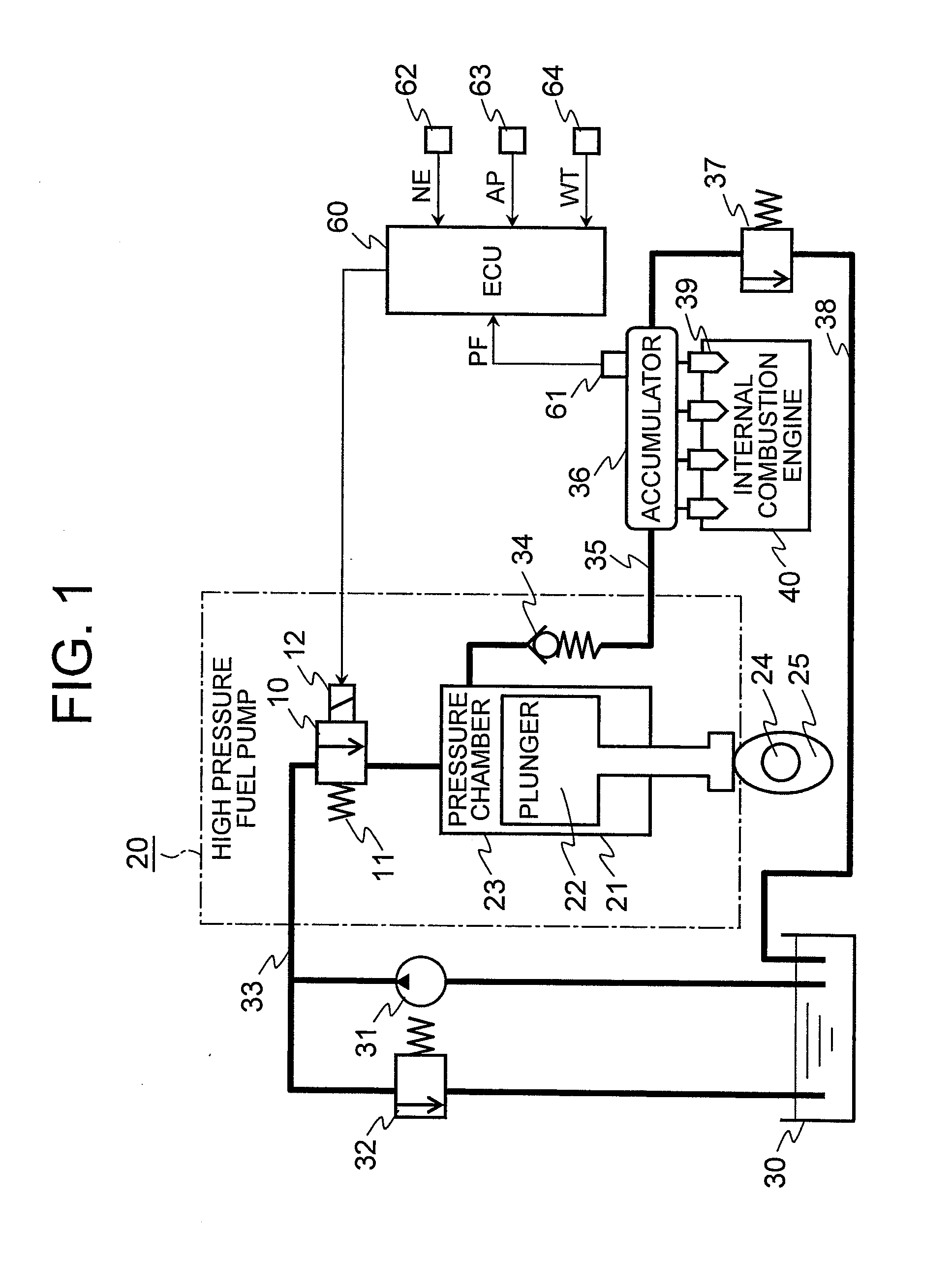
[0030]Referring to the drawings and first to FIG. 1, there is schematically shown a high pressure fuel pump control apparatus for an engine according to a first embodiment of the present invention.

[0031]In FIG. 1, the high pressure fuel pump control apparatus for an internal combustion engine includes, as a fuel supply system for an internal combustion engine 40, a high pressure fuel pump 20 adapted to operate in synchronization with a pump cam 25 formed integral with a camshaft 24 of the internal combustion engine 40, a fuel tank 30 having fuel filled therein, a low pressure passage 33 connected to the fuel tank 30 through a low pressure fuel pump 31 and a low pressure regulator 32, a high pressure passage (delivery passage) 35 connected to an accumulator 36 through a fuel delivery valve 34, a relief passage 38 connecting between the accumulator 36 and the fuel tank 30 through a relief valve 37, and fuel injection valves 39 for supplying by injection the fuel accumulated in the acc...

embodiment 2

[0107]Although in the above-mentioned first embodiment, any concrete configuration of the high pressure fuel pump 20 has not been described, the high pressure fuel pump 20 may be constructed as shown in FIG. 6 through FIG. 8.

[0108]FIG. 6 through FIG. 8 are cross sectional views that show a specific configuration of a high pressure fuel pump 20 according to a second embodiment of the present invention. FIG. 6 shows a state where a solenoid 12 is non-energized, and FIGS. 7 and 8 show mutually different operating states where a plunger 22 is driven to move in an upward direction and in a downward direction, respectively, during energization of the solenoid 12.

[0109]In the FIG. 6 through FIG. 8, the high pressure fuel pump 20 includes a fuel suction port that is placed in fluid communication with a low pressure passage 33 (see FIG. 1), a fuel delivery port that is placed in fluid communication with a high pressure passage 35 (see FIG. 1), the plunger 22 that is driven to reciprocate in ...


PUM


Abstract

In a high pressure fuel pump control apparatus for an internal combustion engine which has a high pressure fuel pump of an engine driven type capable of pressure feeding a controlled amount of fuel by driving a fuel suction valve to close at predetermined timing in a fuel delivery stroke, fuel pressure in an accumulator is swiftly raised by reliably pressure feeding a maximum amount of fuel from a fuel delivery stroke immediately after engine starting while avoiding heat generation by a solenoid for controlling the fuel suction valve, whereby deterioration of a combustion state and exhaust emissions at engine starting can be prevented. A starting time control section continuously energizes the solenoid over a period from the beginning of engine starting until when it becomes possible to perform valve closing timing control on the fuel suction valve based on the rotational position of the engine after completion of cylinder identification.

Description

BACKGROUND OF THE INVENTION[0001]1. Field of the Invention[0002]The present invention relates to a high pressure fuel pump control apparatus for an internal combustion engine of a direct injection type, for example. In particular, the invention relates to a technique for facilitating the rising of fuel pressure when an internal combustion engine is started in a state where the pressure of fuel in an accumulator is low (e.g., after the internal combustion engine has been left stopped).[0003]2. Description of the Related Art[0004]Conventionally, in direct injection type internal combustion engines in which fuel is directly supplied by injection to a combustion chamber in each cylinder, the pressure of fuel is raised by pressurizing the fuel to be supplied to each fuel injection valve up to an optimal pressure (a target pressure) for combustion thereof by using a high pressure fuel pump.[0005]In a high pressure fuel pump control apparatus for this kind of internal combustion engine, wh...

Claims


Application Information

Patent Timeline
IPC IPC(8): F02M63/00
CPCF02D41/009F02D41/062F02D41/221F02M59/366F02D2041/0092F02D2250/31F02D41/3845
Inventor OONO, TAKAHIKO
Owner MITSUBISHI ELECTRIC CORP
Why Eureka
Try Eureka