Liquid crystal display device

a display device and liquid crystal technology, applied in semiconductor devices, instruments, optics, etc., can solve the problems of poor display quality, difficult assembly, and large brightness change, and achieve the effect of improving brightness

Active Publication Date: 2008-09-11
PANASONIC LIQUID CRYSTAL DISPLAY CO LTD +1
View PDF15 Cites 35 Cited by
  • Summary
  • Abstract
  • Description
  • Claims
  • Application Information

AI Technical Summary

Benefits of technology

[0024]As for the liquid crystal display device of the present invention, it is possible to furnish a liquid crystal display device with improved brightness by providing color separation filters between the microlens arrays and the backlights, and reutilizing the light absorbed by the color filters in the prior art.

Problems solved by technology

However, since light from a plurality of microlens arrays is transmitted from one aperture, the angular distribution of light emitted from the aperture becomes discrete, so there is the concern that, depending on the angle from which the display is viewed at the time of viewing, the change in brightness is great and display quality degrades.
Also, since the light coming from a plurality of microlens arrays is made to be transmitted from one aperture, there is a need to align the apertures of the liquid crystal panel, the microlens arrays, and the apertures provided at the light source with extremely high accuracy, so it is considered that there is a problem of assembly being difficult.
As mentioned above, if one tries to improve the utilization efficiency of light transmitted through the aperture part of a liquid crystal display device, in particular in the case of trying to improve the light utilization efficiency by reducing the light absorption of color filters, there has been the issue that the structure becomes complex or that display quality is degraded.

Method used


Image

  • Liquid crystal display device
  • Liquid crystal display device
  • Liquid crystal display device

Examples


first embodiment

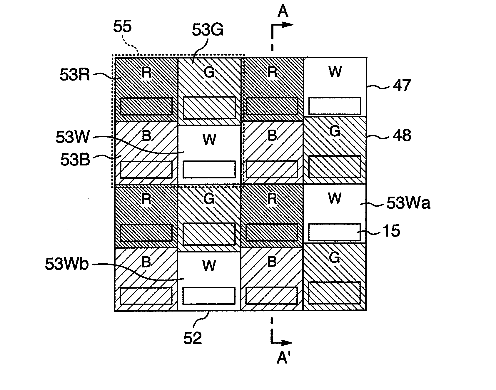
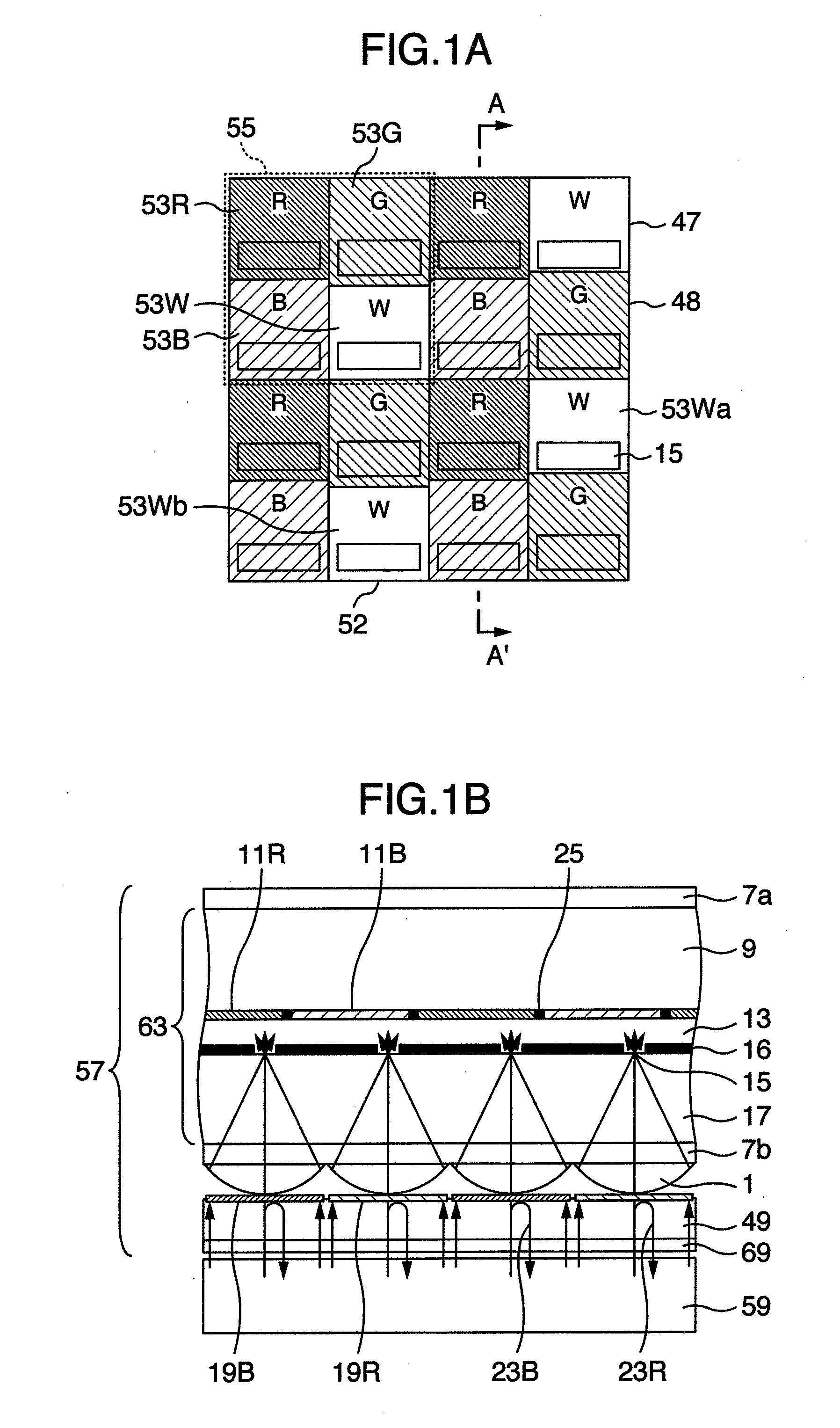
[0045]Using FIG. 1, Embodiment 1 of the present invention will be described. FIG. 1A is a front elevational view of a liquid crystal display device and FIG. 1B is a cross-sectional view, showing a cross section taken along line A-A′ of FIG. 1A, of a backlight and a liquid crystal display element constituting the liquid crystal display device. Here, a transflective type liquid crystal display element having a transmissive display part and a reflective display part is used as a liquid crystal display element 57 and a backlight 59 is used as a backlight.

[0046]One pixel 55 is constituted by four RGBW subpixels 53, the RGBW subpixels 53 being arranged with white (W) subpixels in addition to the red (R), green (G), and blue (B) subpixels, and taking subpixels 53 to be nearly rectangular. R subpixel 53R, G subpixel 53G, and B subpixel 53B are provided with color filters 11 having a desired transmission spectrum, whereas for W subpixel 53W, no color filter is provided. Between each of subpi...

second embodiment

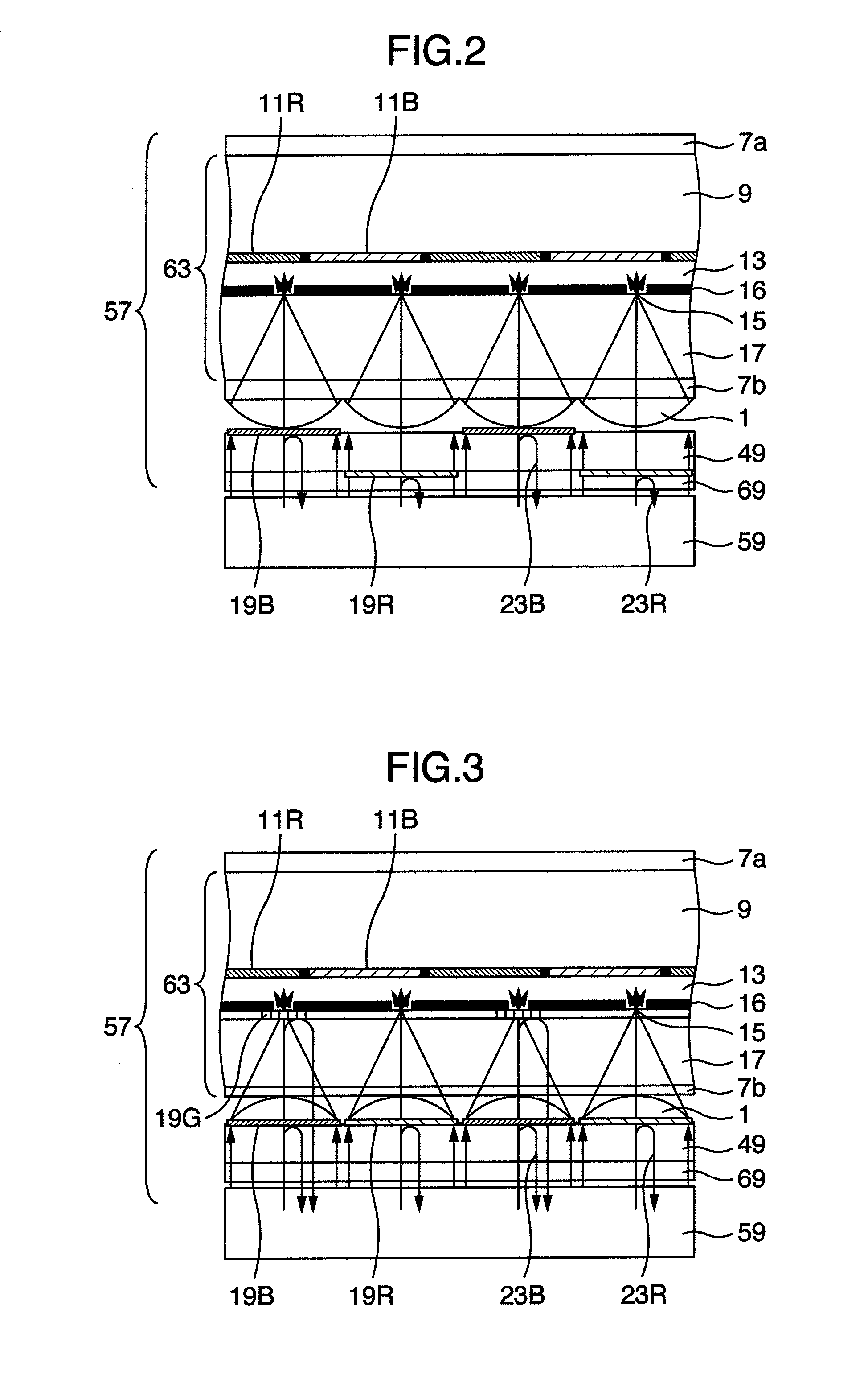
[0076]Using FIG. 2, Embodiment 2 of the present invention will be described. FIG. 2 is a cross-sectional view of a backlight and a liquid crystal display element constituting the liquid crystal display device, a cross section taken along line A-A′ of FIG. 1A being shown. Since only the arrangement of color separation filter 19 differs from Embodiment 1, the description will be given regarding the points of difference.

[0077]In the present embodiment, color separation filter 19B and color separation filter 19R were formed by splitting them off to separate faces of filter substrate 49. In the present embodiment, after forming color separation filter 19B and color separation filter 19R on top of filter substrate 49, they were patterned together. In case the pattern was exposed to light, the exposure was carried out by adjusting the positions so that the color separation filter 19 intervals had the desired positional relationships.

[0078]In this way, by forming two kinds of color separati...

third embodiment

[0079]Using FIG. 3, Embodiment 3 of the present invention will be described. FIG. 3 is a cross-sectional view of a backlight and a liquid crystal display element constituting an liquid crystal display device, showing a cross section taken along line A-A′ of FIG. 1A. A description will be given regarding the points of difference with Embodiment 1.

[0080]In the present embodiment, there was provided a color separation filter 19G reflecting G wavelength light to transmissive aperture parts 15 of R subpixel 53R and B subpixel 53B. Color separation filter 19G was formed on the liquid crystal layer 13 side of lower substrate 17. Since a light beam reflected by color separation filter 19G can return to the backlight 59 side and a part thereof once again be transmitted through lenticular lens 1 and reutilized, it is possible to further raise the light utilization efficiency.

[0081]A color separation filter 19 reflecting a specific wavelength can be obtained by laminating a high refractive ind...


PUM


Abstract

A liquid crystal display device in which: there are provided lenticular lenses 1 and color separation filters, associated with a subpixel row direction, on the backlight 59 side with respect to lenticular lenses 1; and there are arranged, in a RGW row, a color separation filter 19B reflecting B wavelengths, and in a GBW row, a color separation filter 19R reflecting R wavelengths; wherein, together with collecting light in transmissive aperture parts 15 with lenticular lenses 1 and improving the transmitted quantity of light, the light reflected by color separation filters 19 is returned to backlight 59 and reutilized.

Description

BACKGROUND OF THE INVENTION[0001]The present invention pertains to a liquid crystal display device using reflective type or transflective type liquid crystals.[0002]In JP-A-9-197392, there is disclosed a liquid crystal display device characterized in that: it is provided with a first substrate arranged on the incident light side, a second substrate arranged facing the first substrate, and a liquid crystal layer sandwiched between the first substrate and the second substrate; it includes a first color filter layer consisting of an organic material and a second color filter layer consisting of a dielectric multilayered film; and that a microlens array substrate, on which a microlens array is arranged for each pixel, is bonded to the substrate on which the second color filter layer is formed and collects the incident light in an aperture part by means of the microlens arrays.[0003]In JP-A-2002-189216, there is disclosed an electro-optical device characterized by having a light source m...

Claims


Application Information

Patent Timeline
Patent Type & Authority Applications(United States)
IPC IPC(8): G09G3/36
CPCG02F1/133605G02F2201/52G02F2001/133607G02F1/133621G02F1/133607
Inventor SUGITA, TATSUYAADACHI, MASAYAHIROTA, SHOICHI
Owner PANASONIC LIQUID CRYSTAL DISPLAY CO LTD
Why Eureka
Try Eureka