
Liquid crystal display device

a liquid crystal display and display panel technology, applied in non-linear optics, instruments, optics, etc., can solve the problems of large weight and bulk of cathode ray tubes, which have been the mainstream display devices, damage to signal lines, thin film transistors, etc., and achieve the effect of reducing power consumption

Active Publication Date: 2008-09-11
LG DISPLAY CO LTD
View PDF13 Cites 31 Cited by
  • Summary
  • Abstract
  • Description
  • Claims
  • Application Information

AI Technical Summary

Benefits of technology

[0023]An advantage of the present invention is to provide a liquid crystal display device that is adaptive for reducing power consumption.

Problems solved by technology

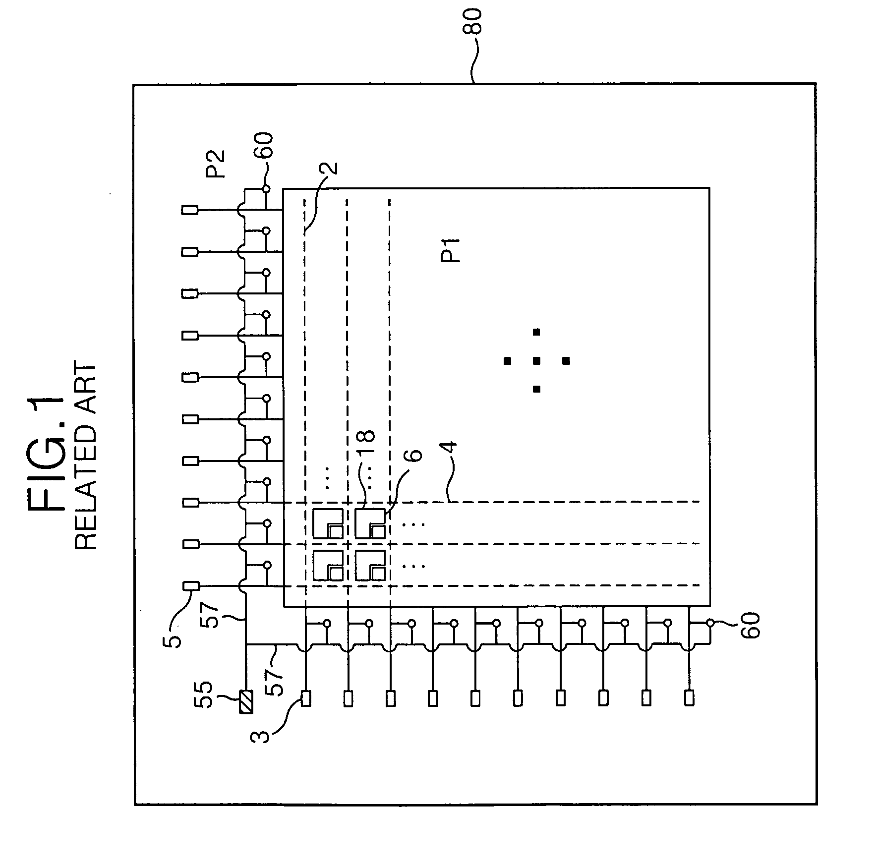
The Cathode Ray Tube (CRT), which has been the mainstream display device, typically has a problematic large weight and bulk.
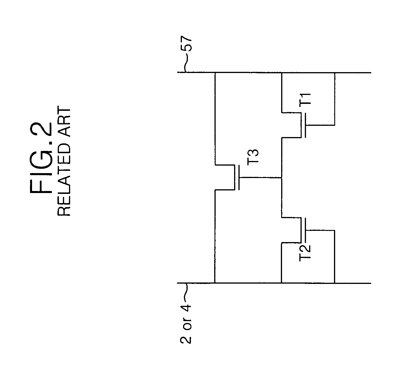
Electrostatic charges of high voltage generated near the liquid crystal display panel of the liquid crystal display device during the manufacturing process or in the manufacturing environment may cause damage to signal lines such as a gate line and a data line within the liquid crystal display panel, to thin film transistors, and to other liquid crystal display panel components.
As a result of increasing the driving voltage, power consumption is increased when the liquid crystal display panel is driven to realize an image.

Method used


Image

  • Liquid crystal display device
  • Liquid crystal display device
  • Liquid crystal display device

Examples


Embodiment Construction

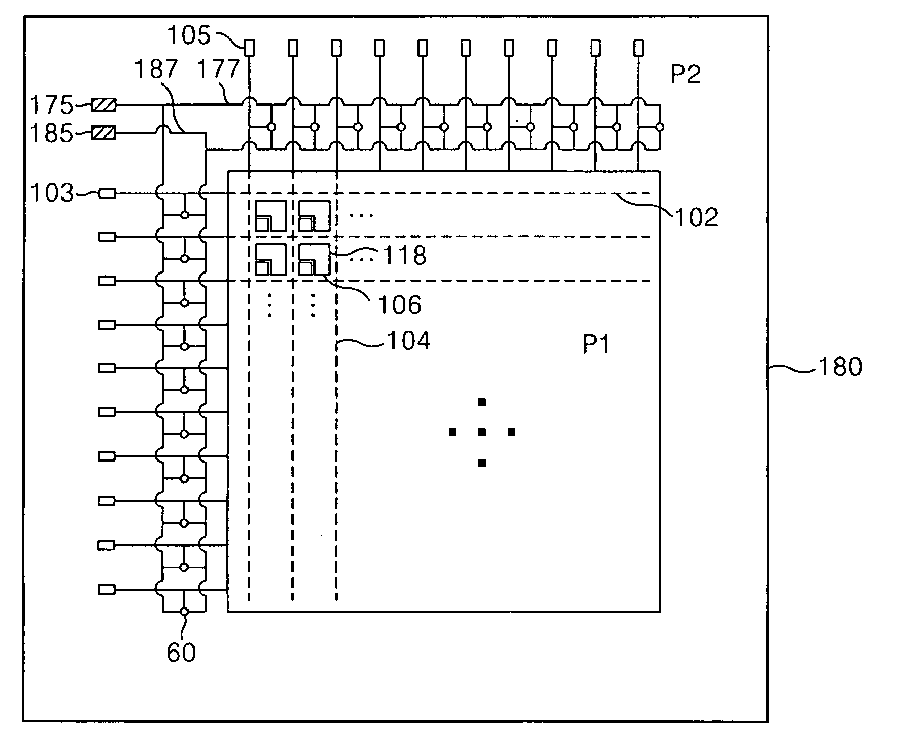
[0044]Reference will now be made in detail to embodiment of the present invention, an example of which is illustrated in the accompanying drawingsFIG. 4 to FIG. 6.

[0045]The liquid crystal display device according to the present invention includes a liquid crystal display panel having liquid crystal cells which are arranged in a matrix type and driving circuits supplying a driving voltage to the liquid crystal display panel. The liquid crystal display panel has liquid crystal cells which are arranged in a matrix type in a display area. An electrostatic discharge protection circuit and the associated pads are located in a non-display area.

[0046]FIG. 4 is a plan view showing a liquid crystal display panel of a liquid crystal display device according to an embodiment of the present invention. More particularly, FIG. 4 shows a thin film transistor array substrate of the liquid crystal display panel.

[0047]The liquid crystal cells which are arranged in a matrix on a display area P1 of the ...


PUM

PropertyMeasurementUnit
threshold voltageaaaaaaaaaa
driving voltageaaaaaaaaaa
voltage Vghaaaaaaaaaa

Abstract

A liquid crystal display device for reducing power consumption is disclosed.In the liquid crystal display device, a liquid crystal display panel has liquid crystal cells which are defined by a gate line and a data line and which are arranged in a matrix type. An electrostatic discharge protection circuit is mounted on the liquid crystal display panel and is connected to any one of the gate line and the data line. A first voltage supply line supplies the same voltage as a first gate voltage with which the gate line is supplied to the electrostatic discharge protection circuit. And a second voltage supply line supplies the same voltage as a second gate voltage with which the gate line is supplied to the electrostatic discharge protection circuit.

Description

[0001]This application claims the benefit of Korean Patent Application No. P2006-138722 filed on Dec. 29, 2006, which is hereby incorporated by reference for all purposes as if fully set forth herein.BACKGROUND OF THE INVENTION[0002]1. Field of the Invention[0003]The present invention relates to a liquid crystal display device, and more particularly to an electrostatic discharge protection circuit for a liquid crystal display device.[0004]2. Description of the Related Art[0005]The display device has become very important as a visual information communicating media in information society. The Cathode Ray Tube (CRT), which has been the mainstream display device, typically has a problematic large weight and bulk. Accordingly, various flat panel display devices have been developed capable of eliminating the weight and bulk disadvantages associated with CRT based displays.[0006]Flat panel display devices include a liquid crystal display device (hereinafter, referred to as “LCD”), a field...

Claims


Application Information

Patent Timeline
Patent Type & Authority Applications(United States)
IPC IPC(8): G02F1/1333
CPCG02F1/136204G02F1/133
Inventor KIM, WOONG SIKLEE, DO YOUNGLEE, KYUNG HOKIM, BUM SIK
Owner LG DISPLAY CO LTD
Learn More