System and Method for Calibration of a Flow Device

Inactive Publication Date: 2008-09-11
ENTEGRIS INC
View PDF14 Cites 38 Cited by
  • Summary
  • Abstract
  • Description
  • Claims
  • Application Information

AI Technical Summary

Benefits of technology

[0005]Embodiments of the present invention provide a system and method for rapid calibration of a flow device that elim

Problems solved by technology

This can be a time consum

Method used


Image

  • System and Method for Calibration of a Flow Device
  • System and Method for Calibration of a Flow Device
  • System and Method for Calibration of a Flow Device

Examples


Example

[0031]Preferred embodiments of the invention are illustrated in the FIGURES, like numerals being used to refer to like and corresponding parts of the various drawings.

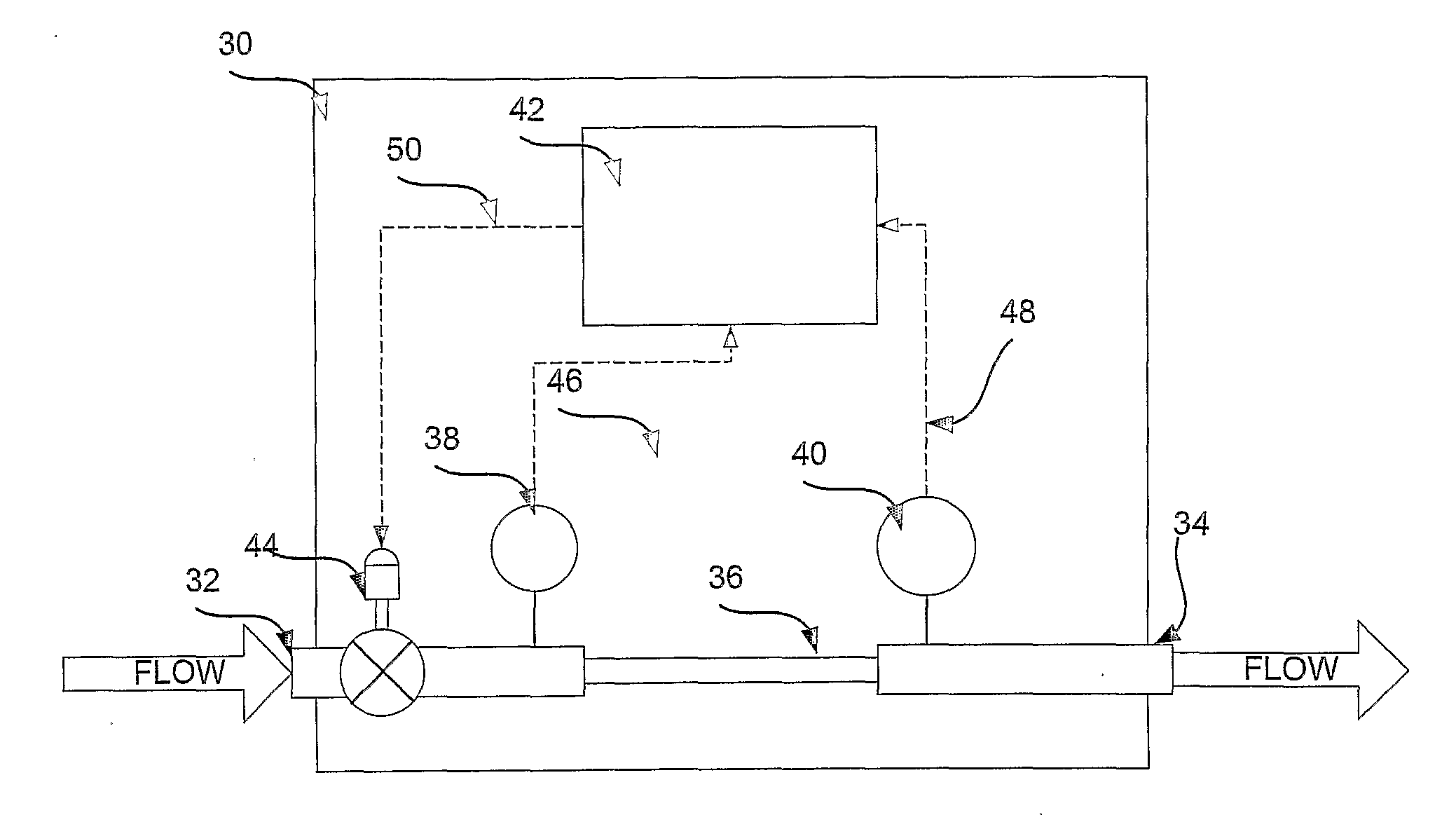
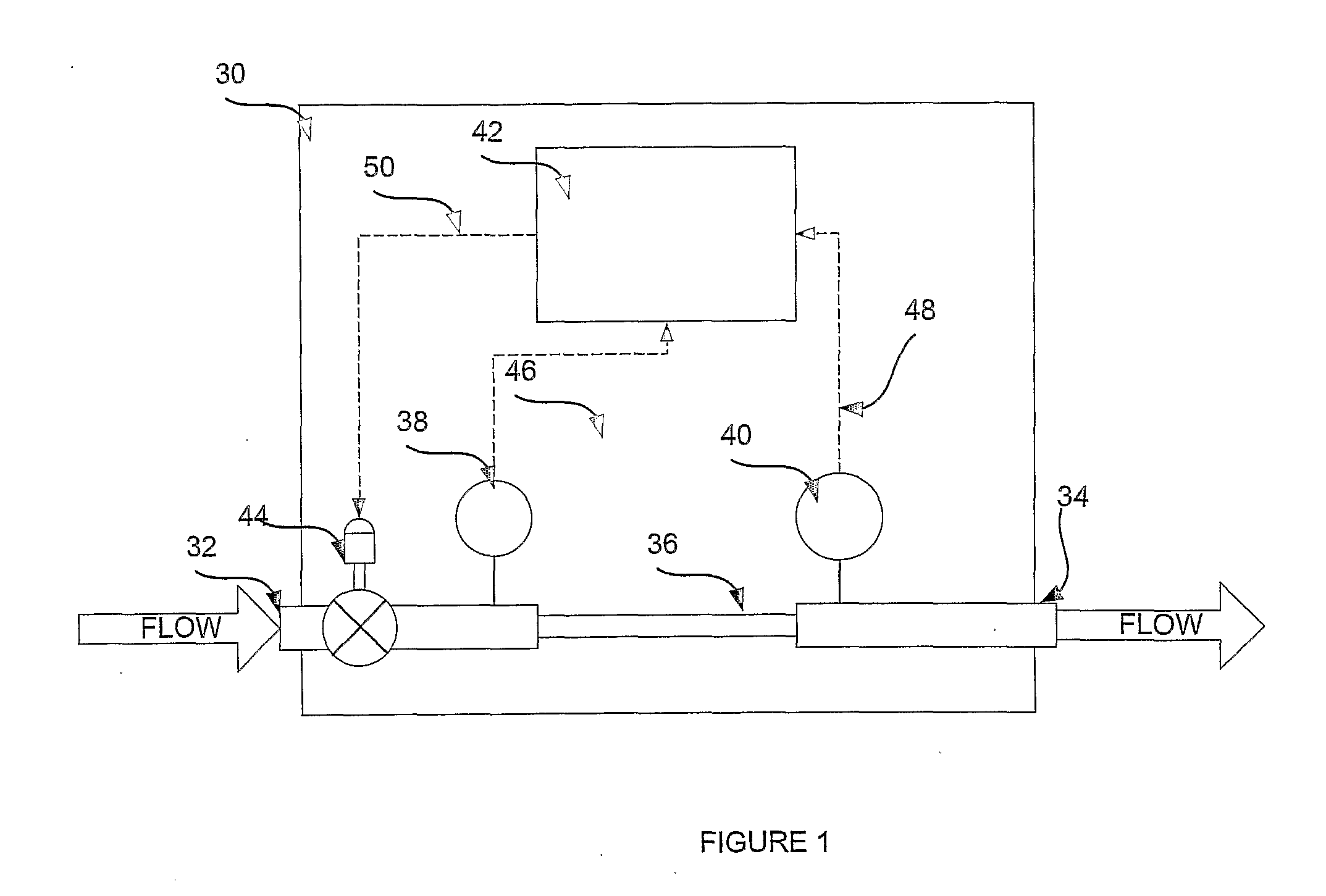
[0032]Flow devices, such as flow meters and flow controllers, typically include a microprocessor based controller that processes readings from one or more sensors to determine the flow rate of a fluid through the device. The controller will apply a flow curve to some variable indicative of flow (e.g., pressure differential, pressure, temperature differential, etc.), usually in the form of an nth degree polynomial, to determine the flow rate. To ensure that the measured flow rate is accurate, the flow curve must account for the process fluid being used and the system in which the flow device is installed.

[0033]Prior to the present invention, either the flow device manufacturer would have to develop a flow curve for the intended process fluid using a test rig similar to the system in which flow device was to be installed...


PUM


Abstract

Embodiments of the present invention provide a system and method for rapid calibration of a flow device. A flow device can be provided with a calibration flow curve (e.g., represented by an nth degree polynomial) by the manufacturer or a third party. The calibration curve can be adjusted for a process fluid and the system for which the flow device is actually installed using one or more correction factors. The correction factors can be determined for the flow curve based on a simple empirical test or fluid properties of the process fluid. The corrected flow curve is then saved at the flow device so that it can be used for future flow control.

Description

RELATED APPLICATIONS[0001]This application claims, under 35 U.S.C 119(e), benefit of and priority to U.S. Provisional Patent Application No. 60 / 601,424, entitled “System and Method for Calibration of a Flow Device,” by Lavardiere et al., filed Aug. 13, 2004, which is hereby fully incorporated by reference herein.TECHNICAL FIELD[0002]The present invention is related to calibration of flow devices and, more particularly, to the rapid calibration of mass flow meters and mass flow controllers.BACKGROUND[0003]Flow controllers are used in a variety of industries to control the flow rate of liquids and gasses. One industry that relies heavily on flow controllers is the semiconductor manufacturing industry. This is because the manufacture of semiconductors requires accurate control of gasses and fluids being dispensed in a flow chamber. Many current flow controllers control flow on a differential pressure basis. These flow controllers receive a set point from a semiconductor manufacturing t...

Claims


Application Information

Patent Timeline
IPC IPC(8): G01F25/00
CPCG01F1/34G05B13/024G01F25/0007G01F25/10G01F25/00
Inventor LAVERDIERE, MARCMCLOUGHLIN, ROBERT F.NIERMEYER, J. KARL
Owner ENTEGRIS INC
Why Eureka
Try Eureka