Williams Link VIII, automotive fluids shuttle

a technology of automotive fluids and shuttles, applied in liquid handling, machines/engines, packaging goods types, etc., can solve the problems of significantly slowing the maintenance process and spills on the shop floor, so as to prevent spills, save costs, and save tim

Inactive Publication Date: 2008-09-18
WILLIAMS JUDY E +1
View PDF6 Cites 13 Cited by
  • Summary
  • Abstract
  • Description
  • Claims
  • Application Information

AI Technical Summary

Benefits of technology

[0007]The present invention overcomes the problems associated with the prior art. Through a plurality of components, the present invention presents a method and apparatus for transferring oils, fuel, and coolant from fluid reservoirs found in mobile or stationery devices powered by internal combustion engines or electric motors by means of a machine that will prevent spills, threats to the environment, human contact with contaminating fluids, clean up costs, and lost time. The present invention accomplishes this spill-free and drip-free transfer of fluids by providing an automotive fluids transfer machine to work in conjunction with the inventors' prior inventions, the Williams Link II, patent application Ser. No. 11/208,938, a vacuum-actuated oil pan valve, the Williams Link III, patent application Ser. No. 11/787,160, a revision of the Williams Link II, the Williams Link VI, patent application Ser. No. 11/998,284, an oil and fuel filter that is a crimped-in fitting for an evacuation and refill system, and the Williams Link VI, patent application No. 60/903,861, an ...

Problems solved by technology

Safe, environmentally sound methods for removal of these fluids are issues that have plagued the various industries that manufacture, use, operate or sell combustion engines and the technicians responsible for the removal of these fluids on a routine basis.
Removing these fluids from their respective reservoirs and placing the fluids in a leak-proof, spill-proof storage receptacle without spilling them in the process has long been a key problem and environmental concern.
The prior art's process of draining waste fluids into a drain pan and the transfer from the drain pan into the holding tan...

Method used


Image

  • Williams Link VIII, automotive fluids shuttle
  • Williams Link VIII, automotive fluids shuttle
  • Williams Link VIII, automotive fluids shuttle

Examples


Embodiment Construction

[0014]Overview: The present invention is the shuttle, a transportable machine designed to receive and transfer waste fluids and fresh fluids found in reservoirs that are related to internal combustion engine or electric motor powered devices. The present invention consists of a parent tank and two auxiliary tanks that vary in size, depending on the vehicles or equipment for which the apparatus is custom-designed, hoses, fittings, a waste fluids manifold, diaphragm pumps and a 4-way control valve.

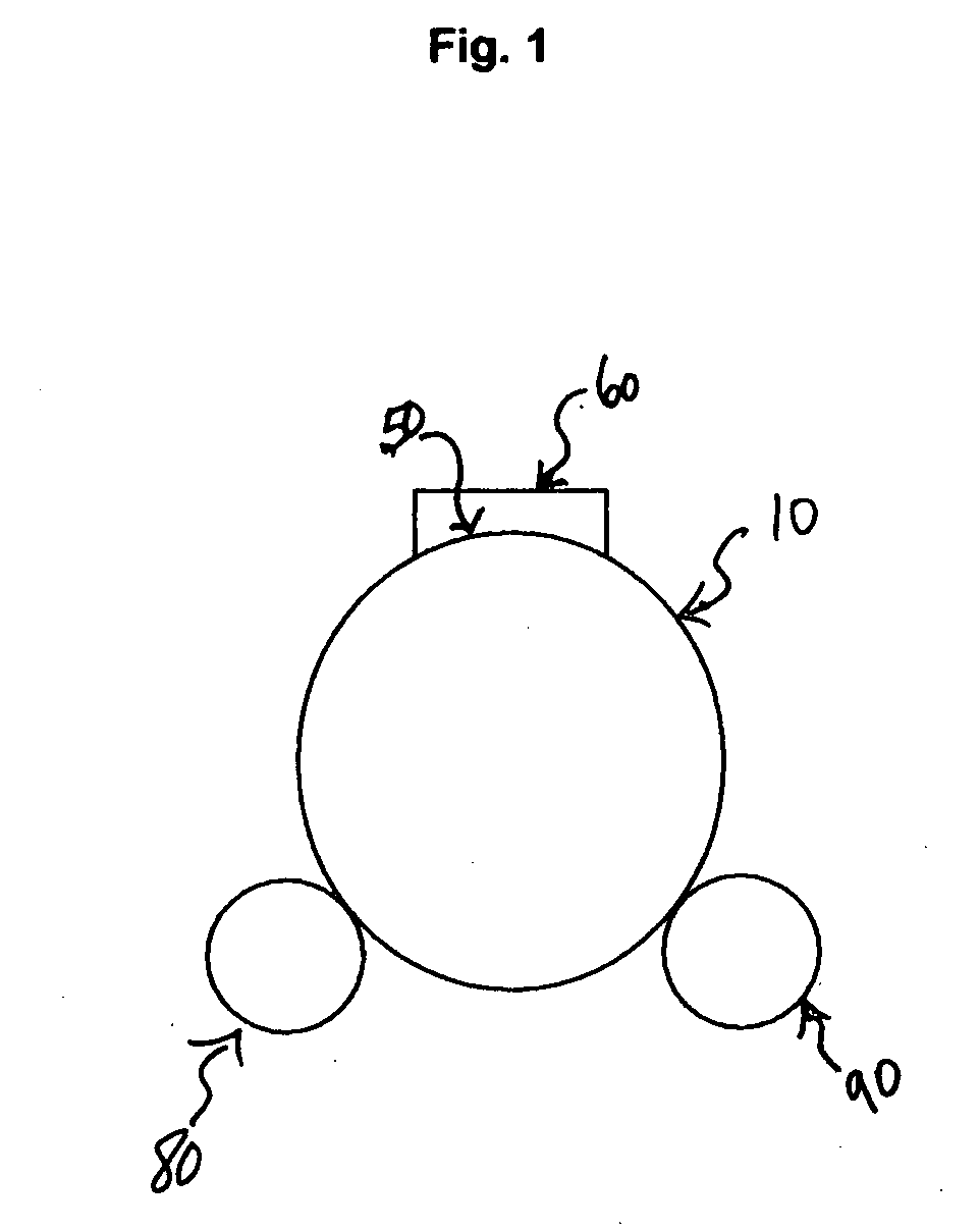
[0015]In FIG. 1, a frontal view of the invention 5 is depicted with two auxiliary tanks for filter maintenance. One auxiliary tank 80 holds fresh filter oil and the other, 90, holds fresh filter fuel.

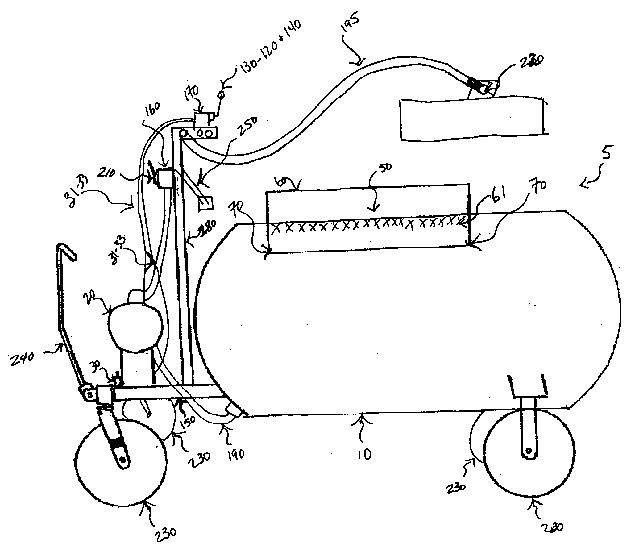
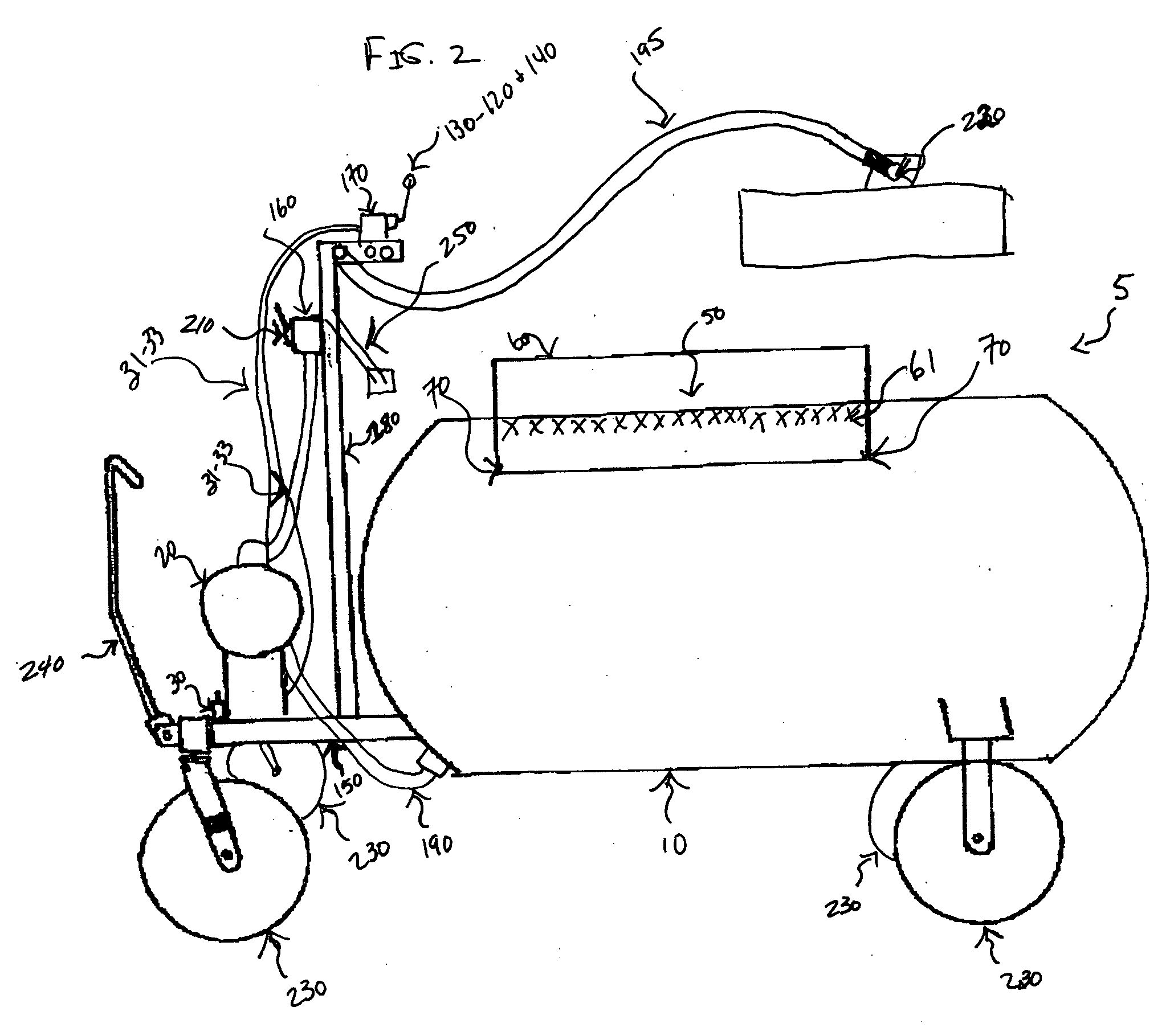
[0016]In FIG. 2, the components of the completed shuttle 5 are depicted. A parent tank 10 is for receiving waste fuel, oil, or coolant that is pumped from an oil, fuel, or coolant reservoir via a vacuum action that is produced by a one inch diaphragm pump 20, which is air operated and is engaged...


PUM

PropertyMeasurementUnit
Pressureaaaaaaaaaa

Abstract

Waste oils, fuels, and coolants contained in reservoirs and filters found in devices powered by electric motors and internal combustion engines are transferred from said reservoirs by a transportable pumping device in the form of an automotive fluids transfer machine, a shuttle, consisting of a parent tank and equipped to receive two auxiliary tanks, one for fresh filter oil and one for fresh filter fuel. The shuttle and auxiliary tanks are made of an oil and fuel resistant and leak proof material so that they can hold waste fluids until they are transferred to a shop's waste fluids disposal tank, without spills, threats to the environment, human contact with contaminating oil fuels or coolants, clean up costs, and lost time.

Description

BACKGROUND OF THE INVENTION[0001]1. Field of the Invention[0002]The present invention relates generally to the environmentally safe removal and replenishment of oils and fuels associated with an internal combustion engine. More specifically, this invention relates to a spill-proof, automotive fluids transfer machine used to hold either waste automotive fluids or fresh automotive fluids, or both, and being comprised of a tank body, a mounting cart or frame, four wheels, a handle bar for maneuvering the cart, a minimum of one pump, quick connect coupling devices, fittings, hoses, and mountings to receive an auxiliary tank package for upgrade.[0003]2. Description of the Related Art[0004]Any discussion of the prior art throughout the specification should in no way be considered as an admission that such prior art is widely known or forms part of common general knowledge in the field.[0005]Oils, fuels, and coolants are the primary fluids that are the lifeblood of an internal combustion e...

Claims


Application Information

Patent Timeline
IPC IPC(8): F01M11/04F16N33/00B65D83/14
CPCF01M11/0458
Inventor WILLIAMS, JUDY E.WILLIAMS, JAMES C.
Owner WILLIAMS JUDY E
Why Eureka
Try Eureka