Wettability Switch

a technology of wetting control and switch, which is applied in the field of wetting control switch, can solve the problems of difficult adaptation to large-scale and cost-effective manufacturing, severe restrictions on the properties of molecule monolayers, and the technique described in the above article is somewhat restricted, etc., to achieve rapid and accurate wetting control, easy to drive and control, and easy to remove

Inactive Publication Date: 2008-09-18
ACREO
View PDF5 Cites 42 Cited by
  • Summary
  • Abstract
  • Description
  • Claims
  • Application Information

AI Technical Summary

Benefits of technology

[0035]However, certain “wetting liquids” (pharmaceuticals, bio materials, reactive chemicals, etc.) do not tolerate a current to be past through them (or even a potential gradient within the liquid). If exposed to an electric field, such liquids may alter their composition and their intended effect will thereby change. For these cases, separating the electrochemically active surface and the wetting surface ensures that the “wetting liquid” can be separated from the ionic current occurring in the electrolyte.
[0036]In order to provide for the electrochemical reaction that drives the wettability switch, there is thus a need for an electrolyte component. The electrochemically active polymer and the electrolyte element thus form an electrochemical system. There are a vast number of electrolytes available. For the purpose of the present invention the electrolytes can be divided into two groups: fluid electrolytes and solid electrolytes. Solid electrolytes are typically applied on the polymer in order to permanently define electrochemically active areas. A fluid electrolyte (e.g. a liquid or a gas) can more easily be applied at will and is obviously easier to remove. Depending on the application at hand, it is even possible to move a liquid electrolyte on the wetting surface by means of wetting property changes induced by the electroly

Problems solved by technology

However, the technique described in the above article is somewhat restricted.
First, there are severe restrictions on the molecule monolayer regarding the molecule properties as well as the molecule density.
Third, the device described is not easily adapted for l

Method used


Image

  • Wettability Switch
  • Wettability Switch
  • Wettability Switch

Examples


Embodiment Construction

[0059]The invention will now be described in further detail. First, various structures will be described in order to exemplify the broad range of structural designs that are envisaged. Second, various materials that can be used for the invention will be discussed. Third, methods of manufacturing are discussed, and fourth, various experiments performed on test structures will be described. Finally, a number of envisaged applications for the wettability switch will be outlined.

Fundamental Structures

[0060]Even though the actual structure that is employed for a certain embodiment may take many different shapes, many of them can be categorized into one of four fundamental structures, which in the following are denoted Structure 1, Structure 2, Structure 3, and Structure 4, respectively.

Structure 1

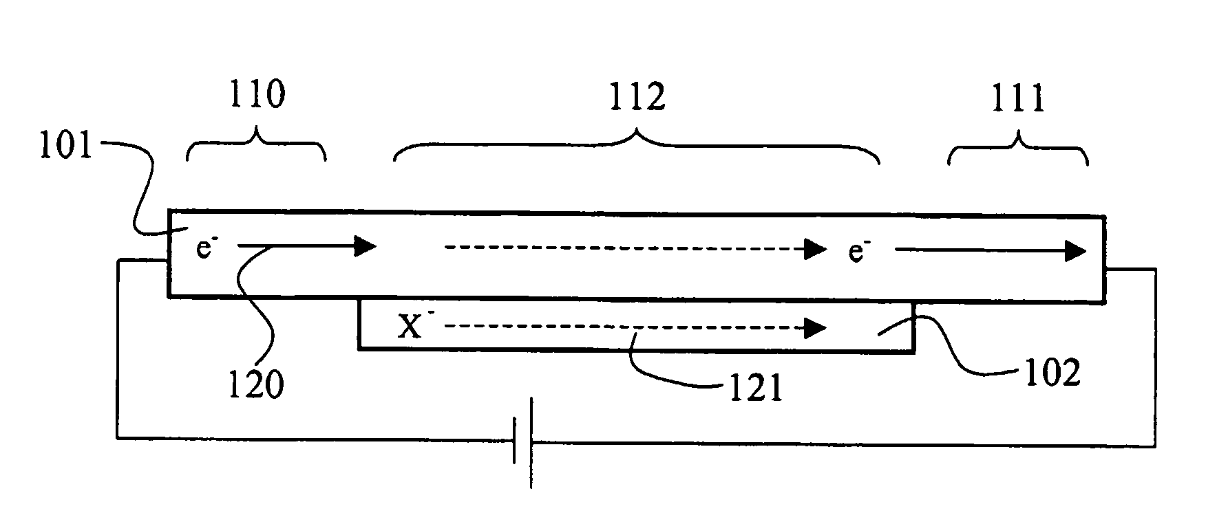
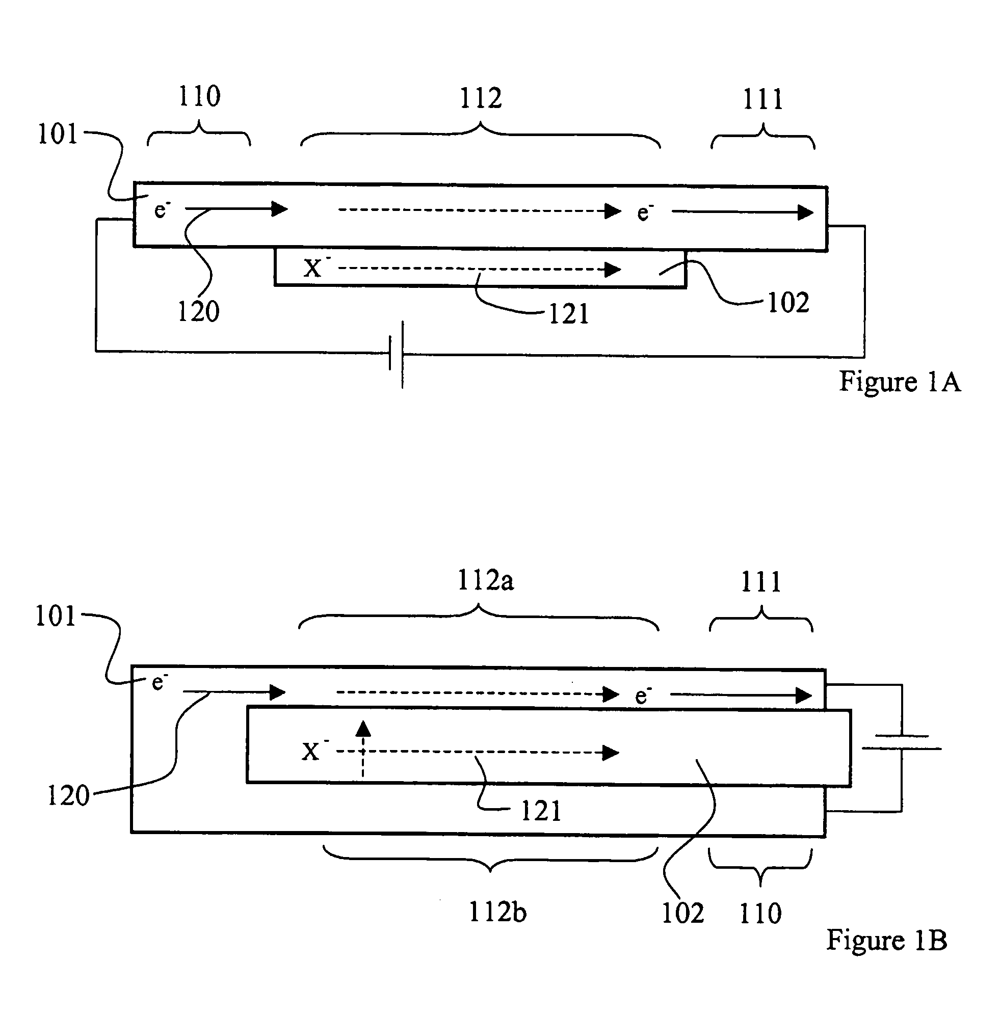
[0061]Structure 1 is illustrated by the cross-sectional views of FIGS. 1a and 1b. The structure comprises an electrochemically active polymer element 101 and an electrolyte element 102. The poly...


PUM

PropertyMeasurementUnit
Wettabilityaaaaaaaaaa
Wetting tensionaaaaaaaaaa

Abstract

The present invention relates to a wettability switch that comprises an electrochemically active element having a wetting surface with switchable wetting properties. The electrochemically active element comprises an electrochemically active polymer, and surface active molecules each having a lyophobic portion and a lyophilic portion. In the wettability switch, each of said surface active molecules exposes one of said lyophobic portion and said lyophilic portion towards said wetting surface, and the identity of said portion depends on an electrochemical state of said polymer.

Description

FIELD OF THE INVENTION[0001]The present invention relates to a wettability switch, and in particular to such a switch that provides for improved switching capabilities and ease of manufacturing.TECHNOLOGICAL BACKGROUND[0002]The prospect of controlling the wetting properties (so-called wetting control) of solid surfaces are currently attracting much focus. There are a vast number of envisaged applications, including bioscience (e.g. cell-growth control and selective adsorption of biomaterial), micro-fluid control (e.g. controllable gates and fluid propulsion) and printing techniques (e.g. updatable printing plates).[0003]The wetting properties of a solid surface can be classified on a scale between lyophobic and lyophilic. A lyophilic surface is a surface that attracts liquids whereas a lyophobic surface rejects liquids. A sub-class of the lyophobic and lyophilic conception is denoted hydrophobic and hydrophilic, respectively, and is restricted to wetting properties for water only. A...

Claims


Application Information

Patent Timeline
IPC IPC(8): C25B9/00B05D5/12C23F1/12C23F1/14B01L3/00B41C1/10C08G73/02
CPCB01L3/502707B01L3/502792C08G73/0266B01L2400/0688B41C1/1041B01L2400/0427
Inventor ISAKSSON, JOAKIMROBINSON, NATHANIELBERGGREN, MAGNUS
Owner ACREO
Why Eureka
Try Eureka