Method of Measuring a Weak Magnetic Field and Magnetic Field Sensor of Improved Sensitivity

a weak magnetic field and sensor technology, applied in the field of weak magnetic field sensors, can solve the problems of troublesome, difficult to solve, and limited precision of the output signal delivered by these sensors, and achieve the effect of improving the sensitivity of magnetoresistive sensors

Inactive Publication Date: 2008-09-18
THALES SA +1
View PDF16 Cites 28 Cited by
  • Summary
  • Abstract
  • Description
  • Claims
  • Application Information

AI Technical Summary

Benefits of technology

[0023]The object of the invention is to improve the sensitivity o

Problems solved by technology

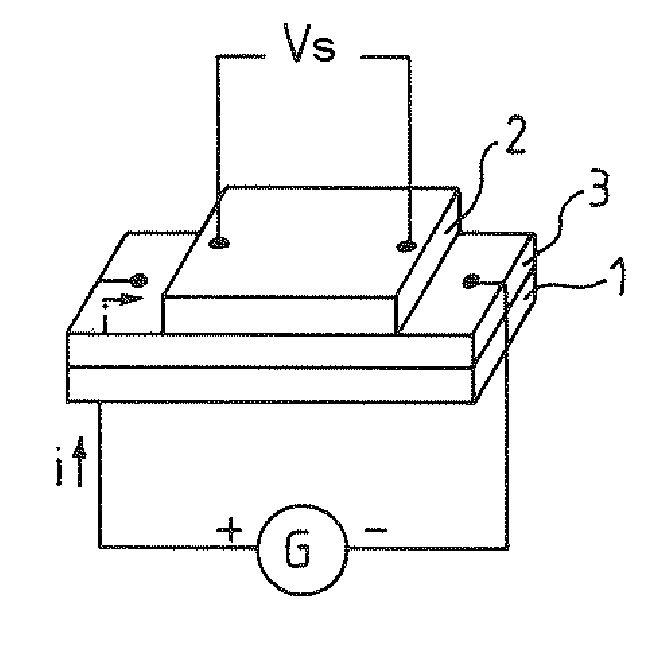
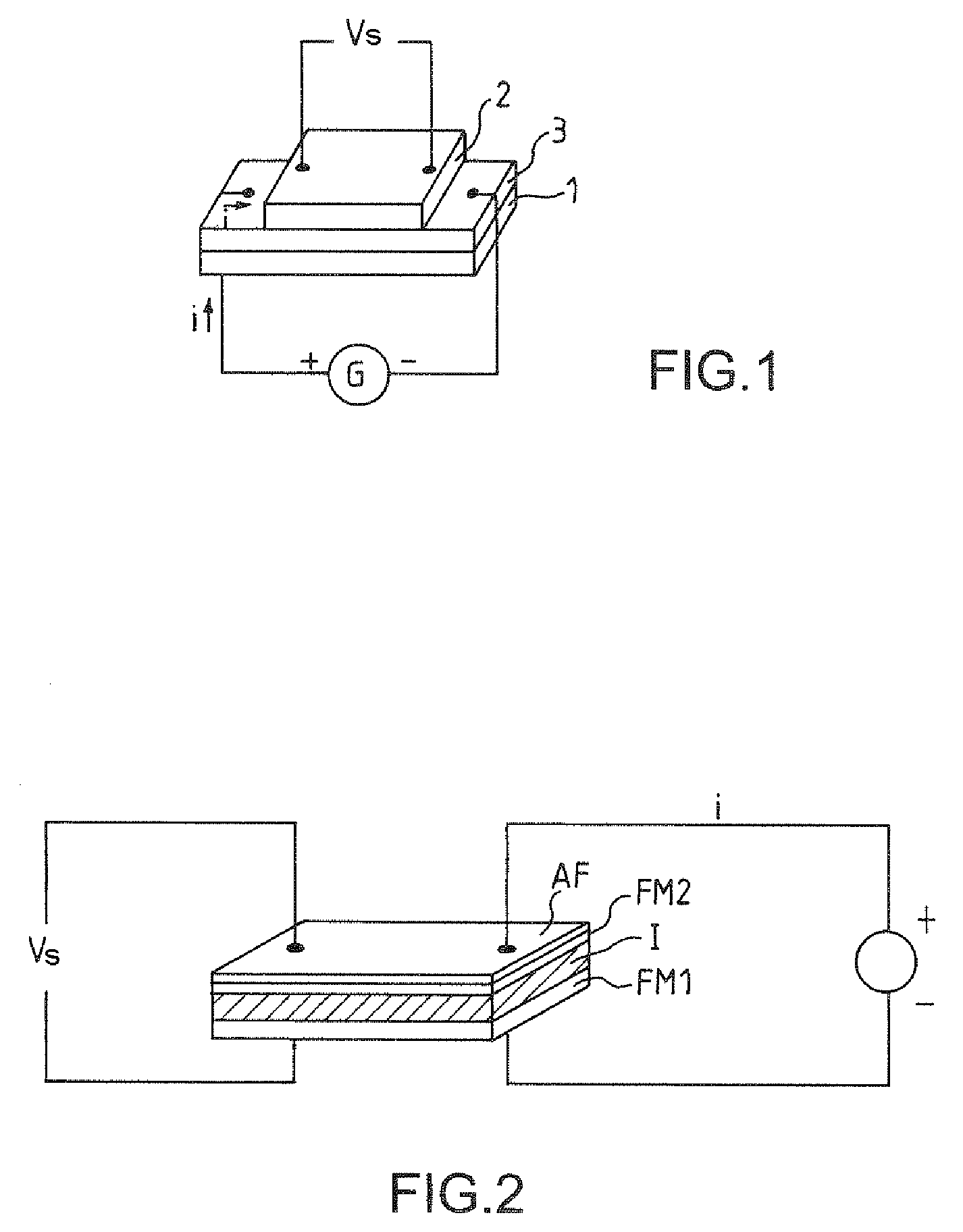
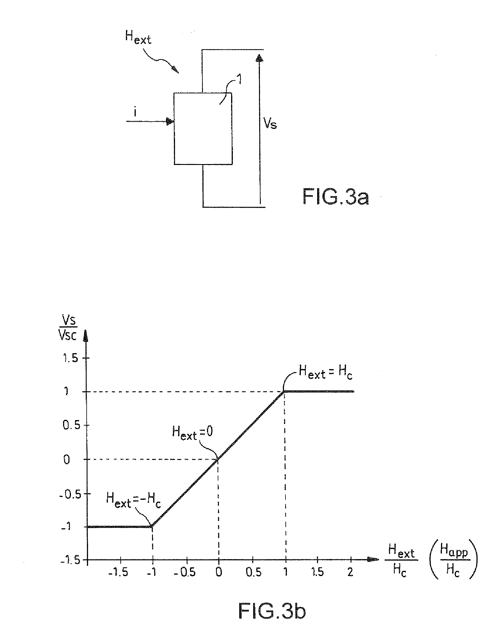
One problem common with such magnetoresistive sensors is that, in weak-field measurement applications for which the sensor operates at low frequency, typically below 1 kilohertz, the precision of the output signal delivered by these sensors is mainly limited by the thermal drift of the signal.
This is particularly troublesome, especially for measuring weak or zero fields.
This is a problem that seems particularly difficult to solve.
However, this method is limited by the coupling between the magnetic layers through the nonmagnetic spacer layer.
However, this solution poses a number of practical problems, especially that of producing the current leads.
However, it is difficult to obtain identical offset resistances to better than 1% in the case of GMR sensors, which amounts to dividing the resistance R0 by 100 in Equation 1.
This problem is more complex in the case of TMR sensors, sin

Method used


Image

  • Method of Measuring a Weak Magnetic Field and Magnetic Field Sensor of Improved Sensitivity
  • Method of Measuring a Weak Magnetic Field and Magnetic Field Sensor of Improved Sensitivity
  • Method of Measuring a Weak Magnetic Field and Magnetic Field Sensor of Improved Sensitivity

Examples


Embodiment Construction

[0047]A sensor for measuring an external magnetic field Hext according to the invention comprises, as illustrated schematically in FIG. 4:[0048]a magnetoresistive element 10 having a magnetoresistance R;[0049]a generator 11 for generating a bias current i;[0050]means 12 for generating a modulation field Hm at a modulation frequency f derived from a clock signal Clk, delivered for example by a local oscillator 13; and[0051]a signal processing device 14 comprising a device for synchronous detection at the modulation frequency f of the output signal Vs of the magnetoresistive element 10. This electronic device delivers the result of the measurement mes(Hext) of the external field Hext.

[0052]In practice, the synchronous detection device is configured to detect the amplitude of an odd harmonic of the output signal. This harmonic is preferably the fundamental h1, detected at the modulation frequency f of the field Hm. In a variant, it is the third harmonic h3 that is detected at the frequ...


PUM


Abstract

A magnetic field sensor comprises a magnetoresistive element (10) biased with a current (i) in order to measure an external magnetic field (Hext). A magnetic modulation field (Hm) is applied to a sensitive region of said sensor and the sensor comprises a synchronous detection device (14) for measuring the amplitude of an odd harmonic of the output signal.

Description

CROSS-REFERENCE TO RELATED APPLICATIONS[0001]The present Application is based on International Application No. PCT / EP2005 / 056890 filed on Dec. 19, 2005 which in turn corresponds to France Application No 0413831 filed on Dec. 23, 2004 and priority is hereby claimed under 35 USC §119 based on these applications. Each of these applications are hereby incorporated by reference in their entirety into the present application.FIELD OF THE INVENTION[0002]The present invention relates to weak-field magnetic field sensors and more particularly to magnetoresistive sensors used for measuring weak fields, that is to say fields not exceeding the Earth's magnetic field.[0003]It should be noted that the notion of a weak field may be connected with the distance between the magnetic source and the sensor, or with the size of the magnetic source itself.BACKGROUND OF THE INVENTION[0004]It will be recalled that a magnetoresistive sensor uses the magnetoresistance of ferromagnetic materials and nanostruc...

Claims


Application Information

Patent Timeline
IPC IPC(8): G01R33/09
CPCG01R33/09
Inventor LEROY, PAULVAN DAU, FREDERIC NGUYENFRIEDERICH, ALAIN
Owner THALES SA
Why Eureka
Try Eureka