Vehicle electric-power conversion apparatus

a technology of electric power conversion and electric power, which is applied in the direction of mechanical equipment, electric generator control, machines/engines, etc., to achieve the effect of simple configuration, simple configuration and more stably performed control of switching elements

Active Publication Date: 2008-09-18
MITSUBISHI ELECTRIC CORP
View PDF12 Cites 26 Cited by
  • Summary
  • Abstract
  • Description
  • Claims
  • Application Information

AI Technical Summary

Benefits of technology

[0011]An electric-power conversion apparatus according to the present invention is configured in such a way as to include a diode-conduction-state detection unit for detecting diode-on timings and diode-off timings corresponding to conduction states of at least one of the plurality of diodes in the case where the rotating electric machine is in electric-power generating operation and the plurality of switching elements are off; and a gate-command creation Unit for creating gate command signals for the plurality of switching elements, based on the diode-on timings and the diode-off timings detected by the diode-conduction-state detection unit, and for feeding the gate command signals to the plurality of switching elements, and in such a way that the electric-power conversion is performed by means of switching operation, of the plurality of switching elements, in accordance with the gate command signals; therefore, control of the switching elements can be performed without being affected by a load fluctuation, whereby a high-reliability vehicle electric-power conversion apparatus can be obtained with a simple configuration.
[0012]Moreover, an electric-power conversion apparatus according to the present invention is configured in such a way as to include a diode-conduction-state detection unit for detecting diode-on timings and diode-off timings corresponding to conduction states of at least one of the plurality of diodes in the case where the rotating electric machine is in electric-power generating operation and the plurality of switching elements are off; and a rotor-position detection unit for generating a rotor-position signal corresponding to the position of the rotor of the rotating electric machine; a timing processing unit for sequentially storing the values of the rotor-position signals each corresponding to the detected diode-on and the detected diode-off timing and for calculating switching-element-on timings and switching-element-off timings for the plurality of switching elements; and a gate-command creation Unit for creating gate command signals for the plurality of switching elements, based on the switching-element-on timings and the switching-element-off timings calculated by the timing processing unit, and for feeding the gate command signals to the plurality of switching elements, and in such a way that the electric-power conversion is performed by means of switching operation, of the plurality of switching elements, in accordance with the gate command signals; therefore, control of the switching elements can more stably be performed without being affected by a load fluctuation, whereby a further high-reliability vehicle electric-power conversion apparatus can be obtained with a simple configuration.

Problems solved by technology

In the case of the conventional apparatus set forth in Patent Document 1 (Japanese Patent Application Laid-Open No. 2002-218797), phase control for the on / off operation of a switching element is performed by use of a position detection means for detecting the rotation position of the rotor of a vehicle rotating electric machine; however, it has been difficult to cope with a case in which, for example, a load fluctuation causes the original mechanical rotation position corresponding to a phase at which the switching element has to be turned on / off to vary in real time.

Method used


Image

  • Vehicle electric-power conversion apparatus
  • Vehicle electric-power conversion apparatus
  • Vehicle electric-power conversion apparatus

Examples


embodiment 1

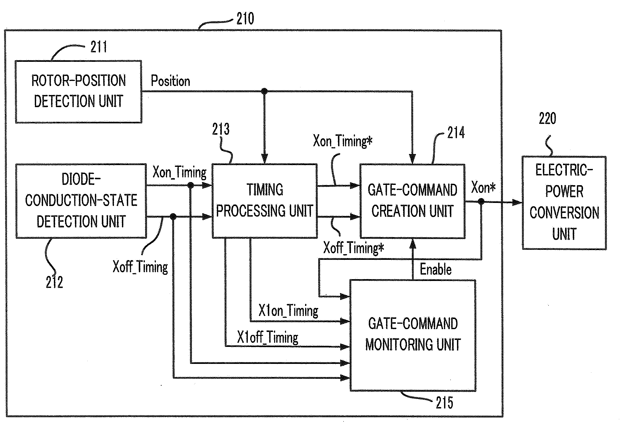
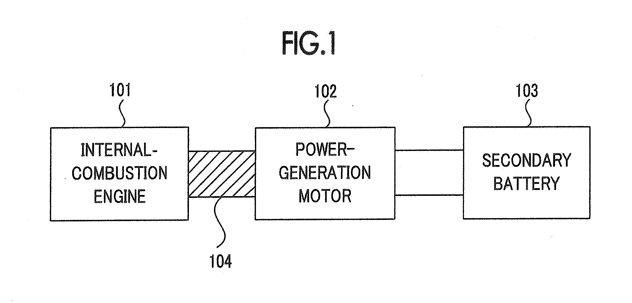
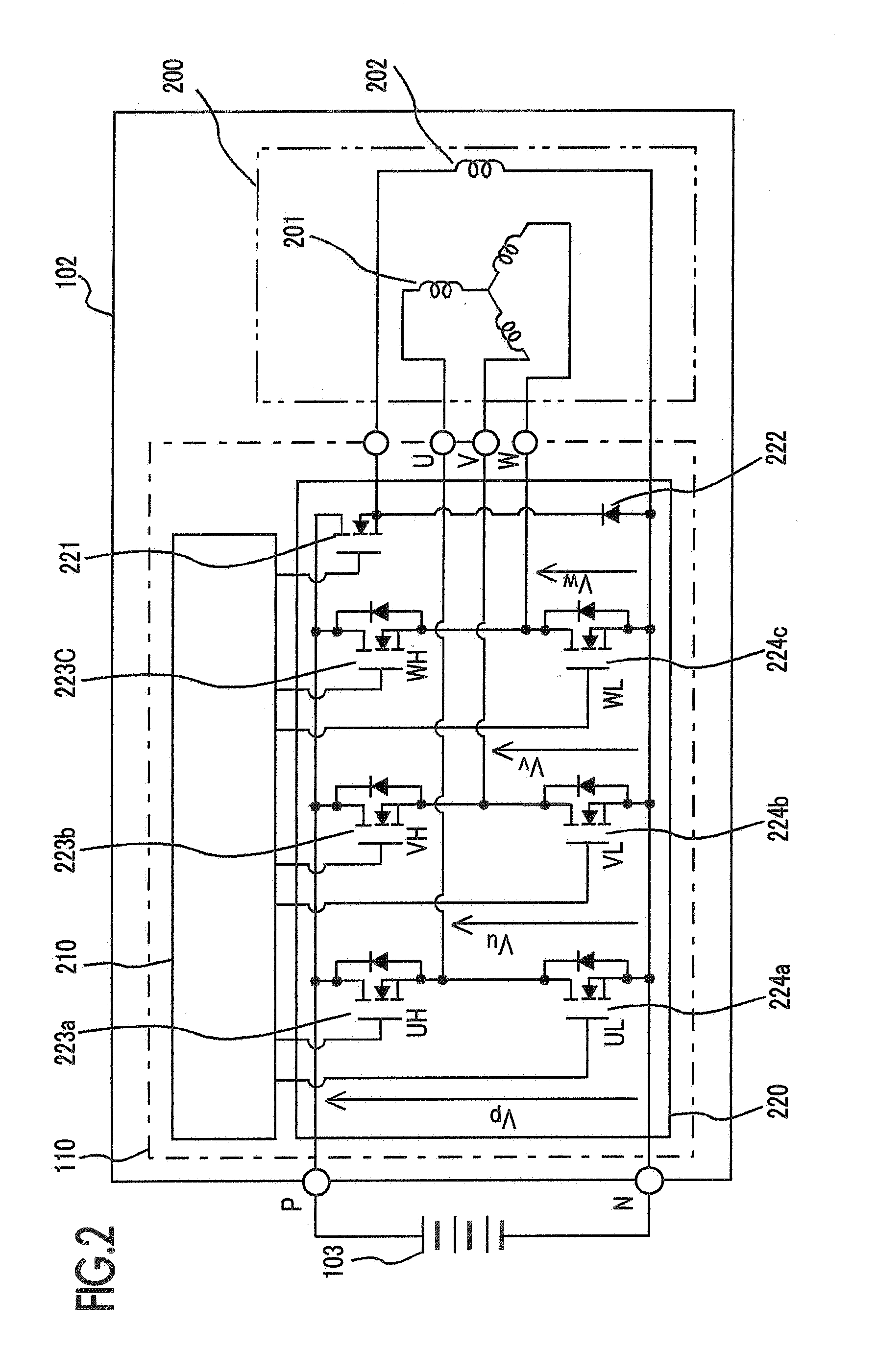
[0028]A vehicle electric-power conversion apparatus according to Embodiment 1 of the present invention will be explained in detail below. FIG. 1 is an explanatory diagram for a vehicle system in which, as a rotating electric machine, a power-generation motor is utilized; FIG. 2 is a configuration diagram illustrating the configuration of a power-generation motor including a vehicle electric-power conversion apparatus according to Embodiment 1 of the present invention; and FIG. 3 is a block diagram illustrating the configuration of the gate control unit in a vehicle electric-power conversion apparatus according to Embodiment 1 of the present invention. In FIG. 1, a power-generation motor 102 as a vehicle rotating electric machine is driven by an internal-combustion engine 101, by way of a power transmission means 104 such as a belt, so as to generate electric power, i.e., AC energy. During the operation of the internal-combustion engine 101, the AC energy generated by the power-gener...

embodiment 2

[0076]In the case of Embodiment 1 described above, the diode-conduction-state detection unit 212 detects respective on-timings and respective off-timings of all the switching diodes and outputs a diode on-timing signal Xon_Timing at each of on-timings t1, t3, t5, t7, t9, and t11 and a diode off-timing signal Xoff_Timing at each of off-timings t2, t4, t6, t8, t10, and t12.

[0077]The diode-on timings and the diode-off timings of lower-arm UL diode, VL diode, and WL diode can be presumed from the diode-on timings and the diode-off timings of the upper-arm diodes; therefore, in a vehicle electric-power conversion apparatus according to Embodiment 2 of the present invention, a diode-conduction-state detection unit 212 actually detects the diode-on timings and the diode-off timings of only upper-arm UH diode, VH diode, and WH diode for phases, U, V, and W, respectively, and based on these timings, presumes the diode-on timings and the diode-off timings of the lower-arm UL diode, VL diode, ...

embodiment 3

[0084]In a vehicle electric-power conversion apparatus according to Embodiment 3 of the present invention, one of the phases U, V, and W is regarded as the representative phase; the actual diode-on timing and the diode-off timing of the diode connected in parallel with the upper-arm switching element corresponding to the specific phase are detected, so that, based on the detected timings, the on-timings and the off-timings of the upper-arm diodes for other phases are presumed, and the actual diode-on timing and the diode-off timing of the diode connected in parallel with the lower-arm switching element corresponding to the specific phase are detected, so that, based on the detected timings, the on-timings and the off-timings of the lower-arm diodes for other phases are presumed.

[0085]FIG. 9 is a timing chart for explaining the operation of a diode-conduction-state detection unit 212 of a vehicle electric-power conversion apparatus according to Embodiment 3 of the present invention. ...


PUM


Abstract

The objective of the present invention is to obtain a vehicle electric-power conversion apparatus in which high-efficiency rectification operation can be realized, by detecting in real time a change, due to a fluctuation in a load, in a phase at which a switching element is turned on / off and by changing the phase at which the switching element is turned on / off, in response to the change. A diode-on timing and a diode-off timing corresponding to the diode conduction state of a diode connected in parallel with a switching element are detected; the values of rotor-position signals corresponding to the timings are sequentially stored; based on the stored values of rotor-position signals, a switching-element-on timing and a switching-element-off timing are calculated; and based on the timings, a gate command signal for the switching element is created.

Description

BACKGROUND OF THE INVENTION[0001]1. Field of the Invention[0002]The present invention relates to a vehicle electric-power conversion apparatus utilized for a vehicle rotating electric machine equipped in a vehicle such as a motor vehicle.[0003]2. Description of the Related Art[0004]In a vehicle rotating electric machine, a full-wave rectification method is generally employed in which, as a rectification element, a diode is utilized; however, in order to further enhance the efficiency, a rectification method has been utilized in which, as a rectification element, a switching element is utilized so as to reduce a loss in a rectification element.[0005]A vehicle electric-power conversion apparatus has already been proposed in which a switching element is utilized as a rectification element, and the switching element is on / off-controlled, based on the rotation position, of the rotor of a vehicle rotating electric machine, which is detected through a position detection means (e.g., refer ...

Claims


Application Information

Patent Timeline
Patent Type & Authority Applications(United States)
IPC IPC(8): H02M7/217H02P9/04
CPCH02J7/1492Y02T10/92H02P9/48H02M7/219
Inventor TSUJIMOTO, KATSUYAWADA, NORIYUKI
Owner MITSUBISHI ELECTRIC CORP
Why Eureka
Try Eureka