Microphone Amplification Arrangement and Integrated Circuit Therefor

a technology of microphone amplifiers and integrated circuits, which is applied in the direction of low frequency amplifiers, electrophonic musical instruments, instruments, etc., can solve the problems of thermal noise in the input signal path, adversely affecting the amplifier portion of the ic, and noise generation

a technology of microphone amplifiers and integrated circuits, which is applied in the direction of low frequency amplifiers, electrophonic musical instruments, instruments, etc., can solve the problems of thermal noise in the input signal path, adversely affecting the amplifier portion of the ic, and noise generation

US20080226100A1Active Publication Date: 2008-09-18NXP USA INC

Image

  • Microphone Amplification Arrangement and Integrated Circuit Therefor
  • Microphone Amplification Arrangement and Integrated Circuit Therefor
  • Microphone Amplification Arrangement and Integrated Circuit Therefor

Examples


Embodiment Construction

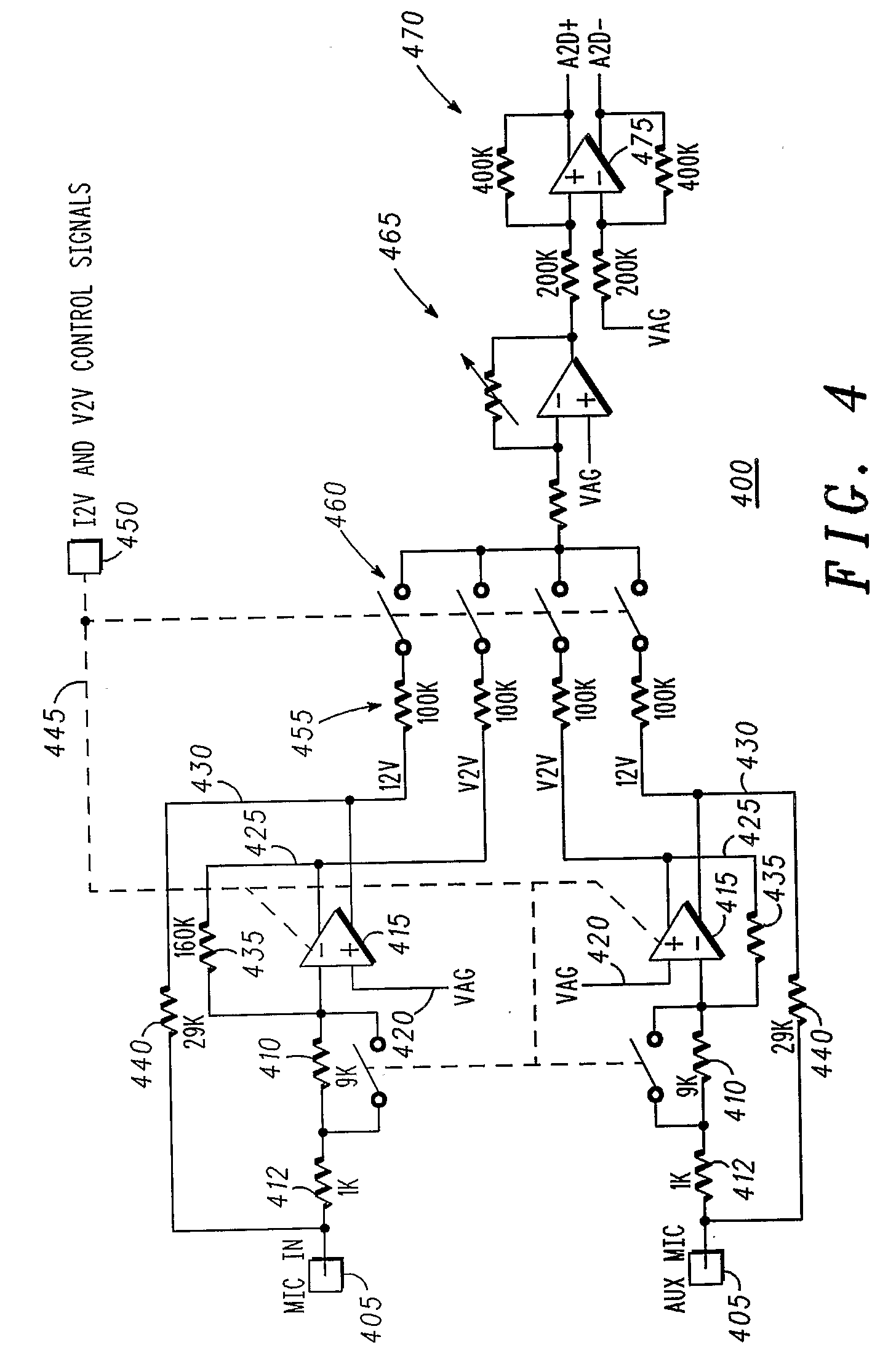
[0027]In summary, the preferred embodiment of the present invention provides a microphone amplification system that supports existing V2V microphone amplifier applications as well as incorporating a selectable low-noise I2V implementation. Advantageously, the proposed microphone amplification system uses only one amplifier core and provides sufficient EMI protection.

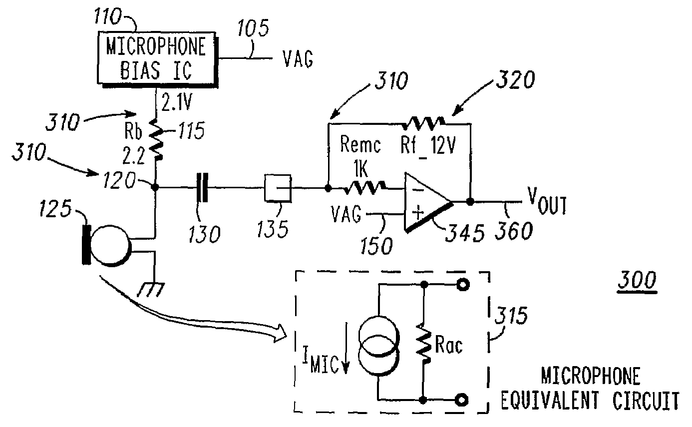
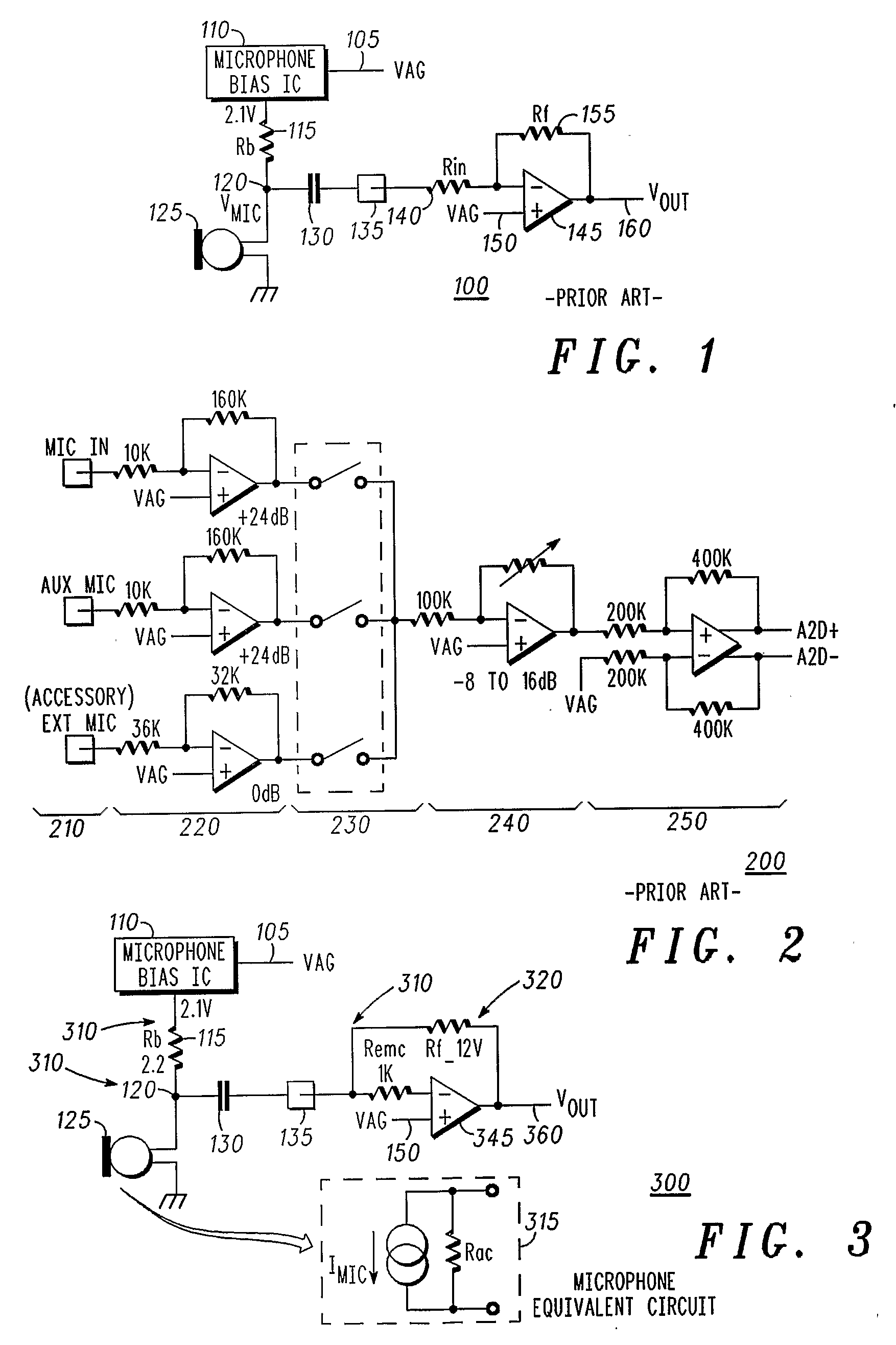
[0028]In mobile phone applications, the microphone is usually an electret condenser microphone, which can be considered as a current source whose value changes with the acoustic pressure applied on the diaphragm. The equivalent circuit includes an equivalent resistance, which is made of the microphone internal resistance Rac in parallel with the biasing resistance Rb and the input resistance Rin of the associated pre-amplifier. The microphone internal resistance Rac and the biasing resistance Rb are set by the microphone manufacturer. Typically Rac>>Rb and Rb=2.2 k.

[0029]Hence, the inventors of the present invention have...


PUM


Abstract

A microphone amplifier arrangement comprises at least one microphone input connected to a dual output microphone pre-amplifier having an input resistance comprising a first resistance and a second resistance in a first voltage-to-voltage mode of operation, and only the second resistance in a second current-to-voltage mode of operation. A first output is operably coupled to a first feedback path comprising a V2V feedback resistor; and a second output is operably coupled to a second feedback path comprising an I2V feedback resistor. In this manner, the microphone amplifier arrangement is arranged to support both a V2V microphone amplifier and a low-noise I2V microphone amplifier.

Description

FIELD OF THE INVENTION[0001]This invention relates to microphone amplifiers. The invention is applicable to, but not limited to, provision of a multimode microphone amplification arrangement.BACKGROUND OF THE INVENTION[0002]There is a wide use of amplifiers in today's electronic circuits. One type of amplifier, known as a “pre-amplifier,” is typically used to amplify (“preamplify”) an unrefined, weak signal that is received from some source, such as a microphone transducer. In a microphone usage, the comparatively small input voltage signal is provided by a microphone transducer to an amplifier referred to as a microphone pre-amplifier. The microphone pre-amplifier amplifies the input analogue audio signal to provide a larger-amplitude “preamplified” output signal that has the same waveform as the input signal, within a particular tolerance.[0003]The preamplified signal is then passed on to a further amplification and / or signal processing stages. For example, the pre-amplified signa...

Claims


Application Information

Patent Timeline
18 Sep 2008
Publication
US20080226100A1
IPC
H03F21/00; H03F99/00
CPC
H03F1/26; H03F3/181; H03F3/45475; H03F2200/03; H04M1/6008; H03F2203/45138; H03F2203/45616; H03F2203/45726
Inventors
ODDOART, LUDOVIC; ENJALBERT, JEROME