Developing device and image forming apparatus

a developing device and image forming technology, applied in the field of electrographic image forming apparatus, can solve the problems of short life of the developing device, degraded toner charging performance, damage to the toner, etc., and achieve the effect of stable toner chargeability, efficient collection, and preventing hysteresis phenomena

Active Publication Date: 2008-09-18
KONICA MINOLTA BUSINESS TECH INC
View PDF4 Cites 12 Cited by
  • Summary
  • Abstract
  • Description
  • Claims
  • Application Information

AI Technical Summary

Benefits of technology

[0018]According to the present invention, the above oscillating electric field is made to act between the first conveyance member and the second conveyance member, so that the toner can be efficiently collected from the second conveyance member without damaging the performance of toner supply from the first conveyance member to the second conveyance member, as a result of which the hysteresis phenomenon can be prevented.
[0019]In the developing device of the present invention, even in the case where the electric field of the toner supply direction is strengthened in order to separate charged particles having a polarity opposite to the toner from the toner, further addition of the charged particles to the developer (corresponding to claim 2) enables the charged particles retained on the carrier surface to impart the toner chargeability stable for a long time without deteriorating the recovery efficiency of the toner.

Problems solved by technology

However, since the toner is subjected to strong stress at the contact position with the friction charge member, the toner is prone to deterioration, and therefore the chargeability of the toner is damaged at a relatively early stage.
Moreover, the toner is attached to the toner bearing member and the friction charge member due to the contact pressure therebetween, by which toner charging performance is degraded and as a result, the life of the developing device becomes relatively short.
However, the two-component development method had an inconvenience, that is, when a magnetic brush is directly brought into contact with an image bearing body for carrying out development, the magnetic brush causes irregular sweeping, resulting in sliding noise generated in images.
This causes such a problem as easy generation of a so-called hysteresis phenomenon in which some of the last developed image appear as an afterimage (memory image) at the time of next development.
However, the charged particles are contained only in the developer initially introduced to the developing device.
Consequently, if a large quantity of an image with small image area ratio or small image ratio (so-called monochrome ratio), such as character images, are printed, then only the charged particles are consumed in large quantities, which causes a problem in obtaining the chargeability of the toner stable for a long time.
However, when the developer density between both the rollers is increased, problems such as torque increase and heat generation by clogging of the developer arise.
However, this proposal impairs the original function, that is, to supply a toner from the magnetic roller to the developing roller.
However, this causes a problem in which the carrier on the magnetic roller tends to be electrostatically adsorbed to the developing roller in connection with the complication of bias control and application of recovery bias.

Method used


Image

  • Developing device and image forming apparatus
  • Developing device and image forming apparatus
  • Developing device and image forming apparatus

Examples


experimental example 1

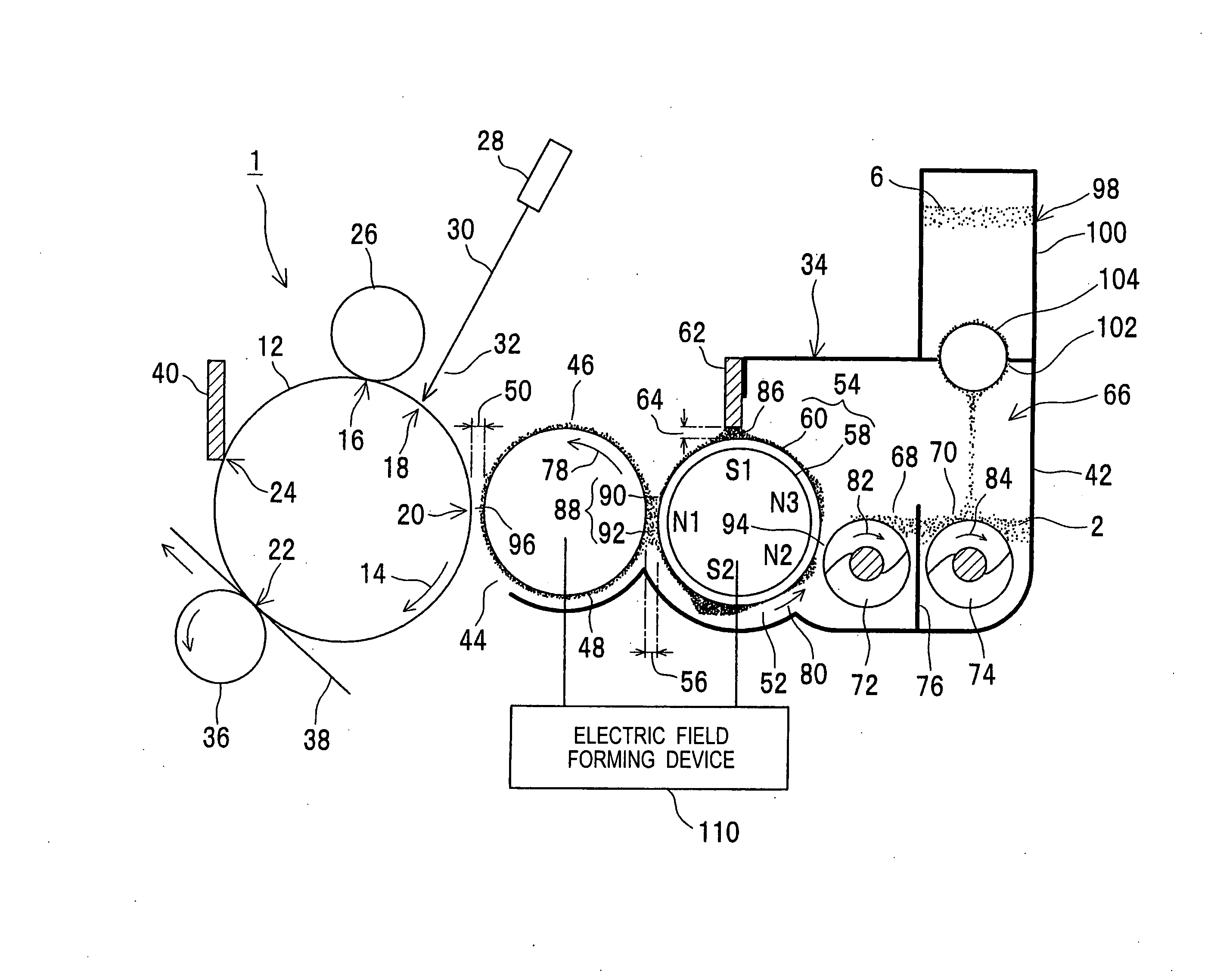
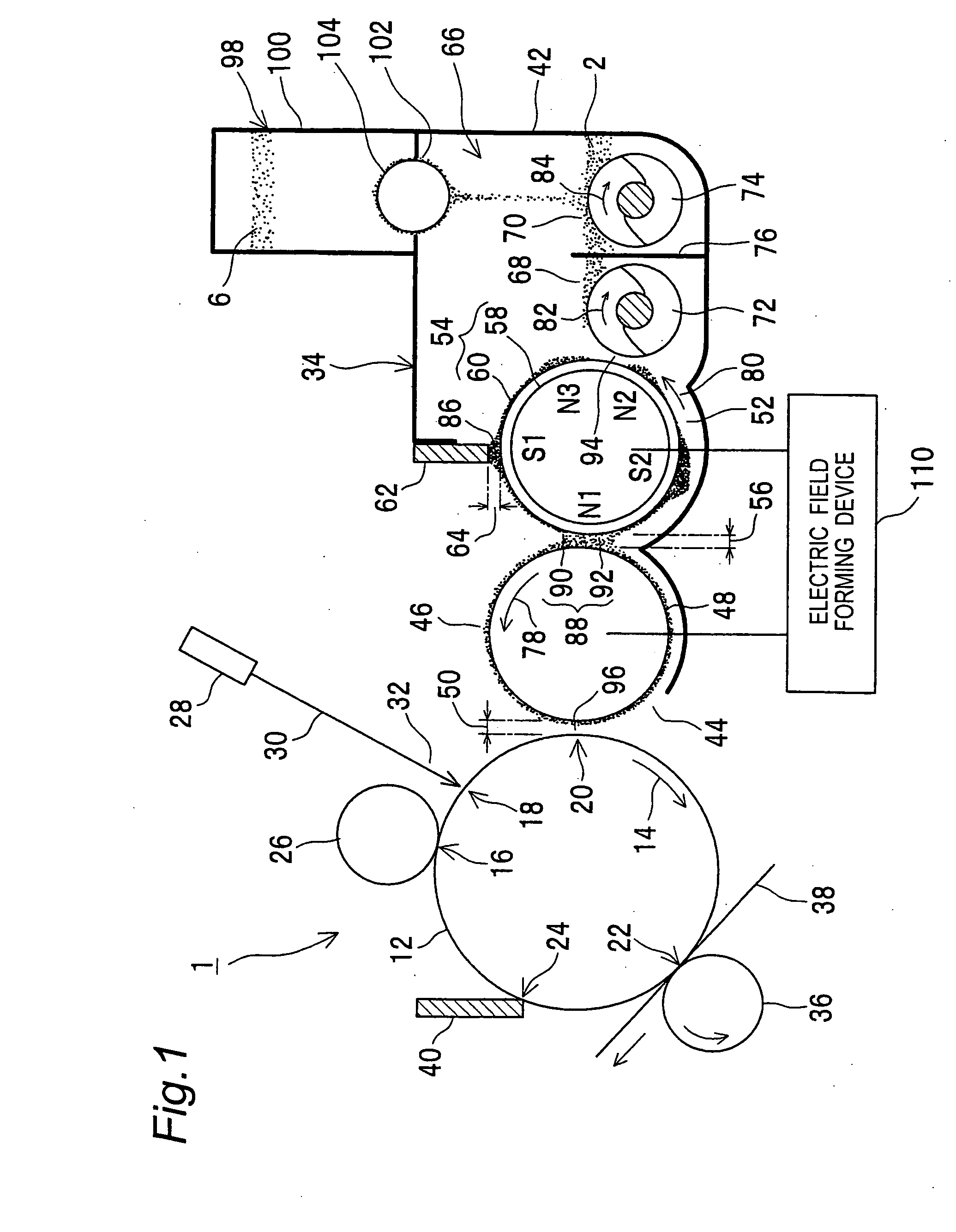
[0116]The supply / recovery gap which is a closest section between the developing roller and the conveying roller was set to 0.3 mm. A developing bias with a DC voltage of −300 v was applied to the developing roller. The experiment was conducted with a so-called contact development structure in which the developing roller comes into contact with the photoconductor via a toner layer.

[0117]Under such conditions, rectangular-wave oscillating biases shown in FIGS. 10(f) and (g) were applied to the conveying roller to form oscillating electric fields as shown in FIGS. 11(f) and (g) in the supply / recovery region, in order to evaluate the recovery performance of development residual toner from the developing roller, and an auxiliary carrier charging function by the charged particle. The oscillating voltage was fixed to a frequency of 2 kHz, an amplitude of 1000 v, and an amplitude median value of −700 v while the duty ratio (expressed as “duty” in each table and drawing below) was varied fro...

experimental example 2

[0121]In an experimental example 2, a developing bias formed by superimposing a rectangular-wave oscillating bias having a frequency of 2 kHz and an amplitude of 1600 v on a DC voltage of −300 v was applied to the developing roller, and a so-called non-contact development structure, in which a development gap in the closest section between the photoconductor and the developing roller was set to 0.15 mm, was formed to conduct an experiment for evaluation similar to that conducted in the experimental example 1. The supply / recovery gap was set to 0.3 mm as in the experimental example 1. While an oscillating bias was used as a bias applied to the developing roller, the bias applied to the conveying roller was adjusted so that the electric field in the supply / recovery region between the developing roller and the conveying roller was identical to that in the experimental example 1. That is, waveform voltages shown in FIGS. 10(b) and (c) were applied to the conveying roller so as to activa...

experimental 3

[0123]An experiment was conducted to examine whether the same function as in the experimental example 2 can be acquired in the case where a device similar to that in the experimental example 2 is used and the frequency of oscillating biases applied to the developing roller and the conveying roller is 3 kHz and 4 kHz. As a result of the experiment, solid charge difference ratios are shown in the table and graph view in FIG. 15 together with the result of the experimental example 2. As is clear from FIG. 15, the recovery side duty ratio efficient for pumping of the toner on the developing roller regardless of the frequency is 60% to 80%.


PUM


Abstract

To provide a developing device capable of preventing the hysteresis phenomenon. The developer of the developing device contains a toner and a carrier. The toner and the carrier are charged to a polarity different from each other by frictional contact thereof. The developing device has a first conveyance member and a second conveyance member which faces an electrostatic latent image bearing body via the second region. An electric field forming device forms a first electric field between the first conveyance member and the second conveyance member to move the toner in the developer retained by the first conveyance member to the second conveyance member, and forms a second electric field between the second conveyance member and the electrostatic latent image bearing body to move the toner retained by the second conveyance member to an electrostatic latent image of the electrostatic latent image bearing body. The first electric field is an oscillating electric field having both a function to supply the toner to the second conveyance member and a function to collect the toner from the second conveyance member while a time average field strength is biased to a side where the toner is supplied from the first conveyance member to the second conveyance member, and a time ratio for carrying out the function to collect the toner from the second conveyance member to the first conveyance member is 60 to 80%.

Description

RELATED APPLICATION[0001]This application is based on Japanese Patent Application No. 2007-67223, the content of which is incorporated herein by reference.BACKGROUND OF THE INVENTION[0002]The present invention relates to an electrophotographic image forming apparatus and a developing device used for the image forming apparatus[0003]As a development method adopted for the electrophotographic image forming apparatus, a monocomponent development method using only a toner as a main component of developer, and a two-component development method using a toner and a carrier as main components of developer are known.[0004]The developing device of the monocomponent development method has a toner bearing member which bears and conveys a toner and a friction charge member which comes into contact with the toner bearing face of the toner bearing member. Upon passing through a contact position with the friction charge member, the toner borne by the toner bearing member comes into frictional cont...

Claims


Application Information

Patent Timeline
Patent Type & Authority Applications(United States)
IPC IPC(8): G03G15/10
CPCG03G15/0907
Inventor GOTO, HIROSHIOKADA, TAKUYA
Owner KONICA MINOLTA BUSINESS TECH INC
Why Eureka
Try Eureka