Space-Variant Liquid Crystal Waveplate

a liquid crystal wave plate and space-variant technology, applied in the field of wave plates, can solve the problems of significant limitations in the application of gratings with sub-wavelength features in the visible in near-infrared wavelength range, and the inability to generate vortex beams of the polarization vortex order greater than m=2

Inactive Publication Date: 2008-09-18
JDS UNIPHASE CORP
View PDF14 Cites 54 Cited by
  • Summary
  • Abstract
  • Description
  • Claims
  • Application Information

AI Technical Summary

Benefits of technology

[0021]One more feature of the present invention provides an optical exposure system for producing a space-variant alignment pattern in an alignment layer of a substrate. The optical exposure system comprises the following elements: a source of polarized radiation suitable for inducing an alignment in the alignment layer; an aperture disposed in an optical path of the polarized radiation between the source of the polarized radiation and the alignment layer shaped for forming on the alignment layer an exposure area radially extending from a center point; rotating means for rotating at least two of: a polarization orientation of the polarized radiation, the aperture, and the alignment layer at selected angular velocities so that the exposure area performs one or more rotations about the center point; and, control means for controlling a ratio of the selected angular velocities so as to produce the space-variant alignment pattern in the alignment layer.

Problems solved by technology

One drawback of this approach is a difficulty in fabrication of gratings with sub-wavelength features in the visible in near-infrared wavelength range; the experiments described by Erez have been performed at far-infrared wavelengths (10.6 μm) for which the grating features are practical to make.
The method indeed provides a waveplate with a continuously varying optic axis orientation, but may only create a very small annulus where π retardance is achieved, and may be sensitive to thermally-induced stresses, which significantly limits its applications.
These approaches have a common disadvantage that vortex beams of the polarization vortex order greater than m=2 cannot be generated, or require multiple optical elements to be generated.
Another disadvantage is the use of TN LC materials for the waveplates, which required two pre-aligned substrates for each waveplate, and.
Furthermore, the TN mode LC is known to have limitations in optical power handling capabilities.

Method used


Image

  • Space-Variant Liquid Crystal Waveplate
  • Space-Variant Liquid Crystal Waveplate
  • Space-Variant Liquid Crystal Waveplate

Examples


Embodiment Construction

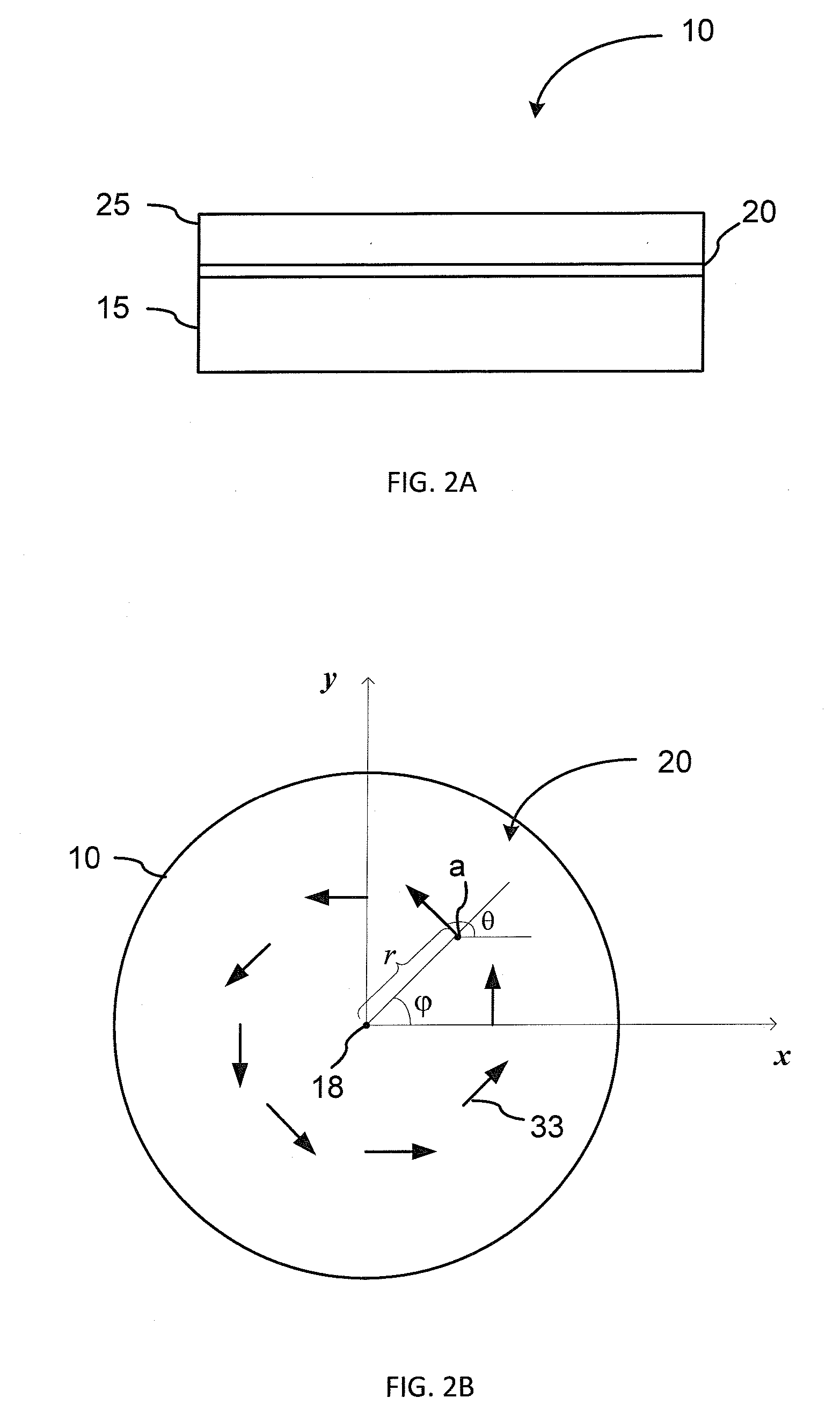
[0041]Turning first to FIG. 2A, the invention provides an apparatus and method for fabricating a space-variant photo-aligned LC (SVLC) waveplate 10 that is capable of forming a polarization vortex beam of substantially any pre-defined vortex order m. In the embodiment illustrated in FIG. 2A the SVLC waveplate 10 utilizes an LC layer 25 of an LC material such as a liquid crystal polymer (LCP), which is disposed on an alignment layer 20 of a photo-alignable material, such as a linear photopolymerizable polymer (LPP), which is in turn disposed on a planar substrate 15. An example of an LPP is polyvinyl 4-methoxy-cinnamate (“PVMC”). A molecular orientation of the LPP is set by exposure to linearly polarized ultraviolet (LPUV) light to form an LC alignment pattern of the LC material that results in a desired spatial pattern of the optic axis (OA) of the waveplate layer 25. In the context of this specification, the words “spatial pattern of the optic axis” or “spatial OA pattern” are used...


PUM

PropertyMeasurementUnit
wavelengthaaaaaaaaaa
angular velocitiesaaaaaaaaaa
wavelength rangeaaaaaaaaaa

Abstract

The invention provides a space-variant liquid-crystal (LC) photo-aligned waveplate having a vortex optic axis pattern, and an apparatus and method for fabricating thereof. The method in it preferred embodiment includes exposing a substrate coated with a photo-alignable material such as LPP to linearly polarized UV radiation through a wedge-shaped aperture, while rotating two of the aperture, the substrate and the polarization of the UV light, so that an exposure area performs a full rotation about a center point on the substrate, at angular velocities selected so as to form a vortex alignment pattern of a pre-defined order. An LC material is then deposited on the substrate in direct contact with the photo-alignable material so that the LC director is aligned according to the photo-induced vortex alignment pattern. The method enables to fabricate vortex waveplate of any pre-defined vortex order.

Description

CROSS-REFERENCE TO RELATED APPLICATIONS[0001]The present invention claims priority from U.S. Provisional Patent Application No. 60 / 894,255 filed Mar. 12th, 2007, entitled “Tailoring Of Far Field Diffraction Pattern Using Azimuthally Varying Fast Axis Orientation In Liquid Crystal Polymer Films”, which is incorporated herein by reference.TECHNICAL FIELD[0002]The present invention generally relates to wave plates having spatially varying orientation of the optic axis, and particularly relates to a photo-aligned space-variant liquid crystal waveplate and a method of fabricating thereof.BACKGROUND OF THE INVENTION[0003]A wave plate, or an optical retarder, is an optical device that alters the polarization state of incident light by adding a pre-determined phase shift between two orthogonal polarization components of an incident light field. Conventionally, the added phase shift is referred to as the waveplate retardance and is measured in fractions of a wavelength, so that a wave plate ...

Claims


Application Information

Patent Timeline
Patent Type & Authority Applications(United States)
IPC IPC(8): G02B27/00C09K19/00
CPCG02B5/3016G02B5/3083Y10T428/10G03F7/70566G03F7/70966G02F2413/09C09K2323/00G02F1/133631G02F1/1335
Inventor SHEMO, DAVID M.MCELDOWNEY, SCOTTZIEBA, JERRY
Owner JDS UNIPHASE CORP
Why Eureka
Try Eureka