[0017]It has been observed that the typical
operating frequency of a phased array device located in a
magnetic resonance imaging system can range between 60 to 200 MHz. The typical
magnetic imaging system operated with a
magnetic field strength of approximately 1.5 Tesla typically uses radio frequency (RF) power transmitters at a frequency of 63.5 MHz. For a field magnetic strength of approximately 3 Tesla, the
transmitter frequency is typically set to 127 MHz. The high power RF
transmitter frequency of the MR system is in the same range as that used for the phased array
hyperthermia device. To simplify such an integrated system of the phased array
hyperthermia with the
MR imaging system, it is proposed to provide a novel method to utilize the MR RF
power output to also provide the needed power to heat the target using the phased array hyperthermia device that is inserted into the MR aperture.
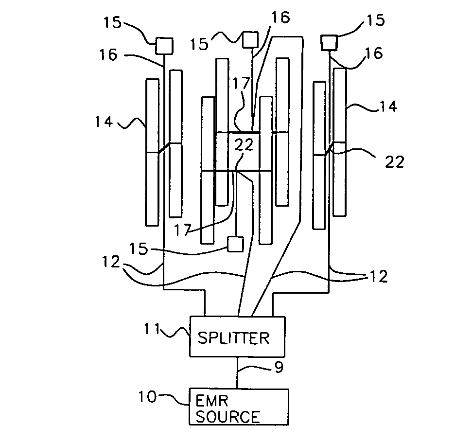
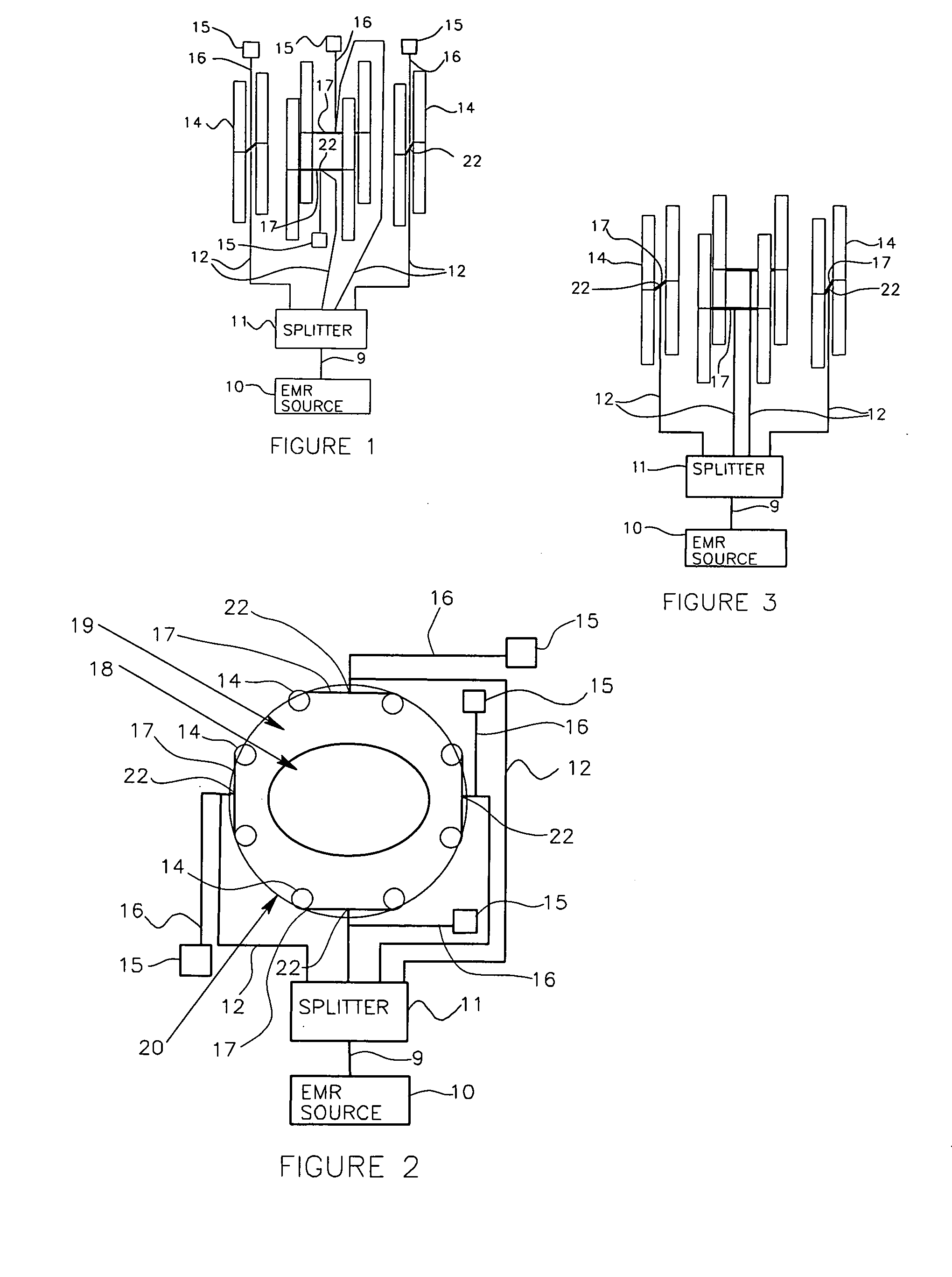
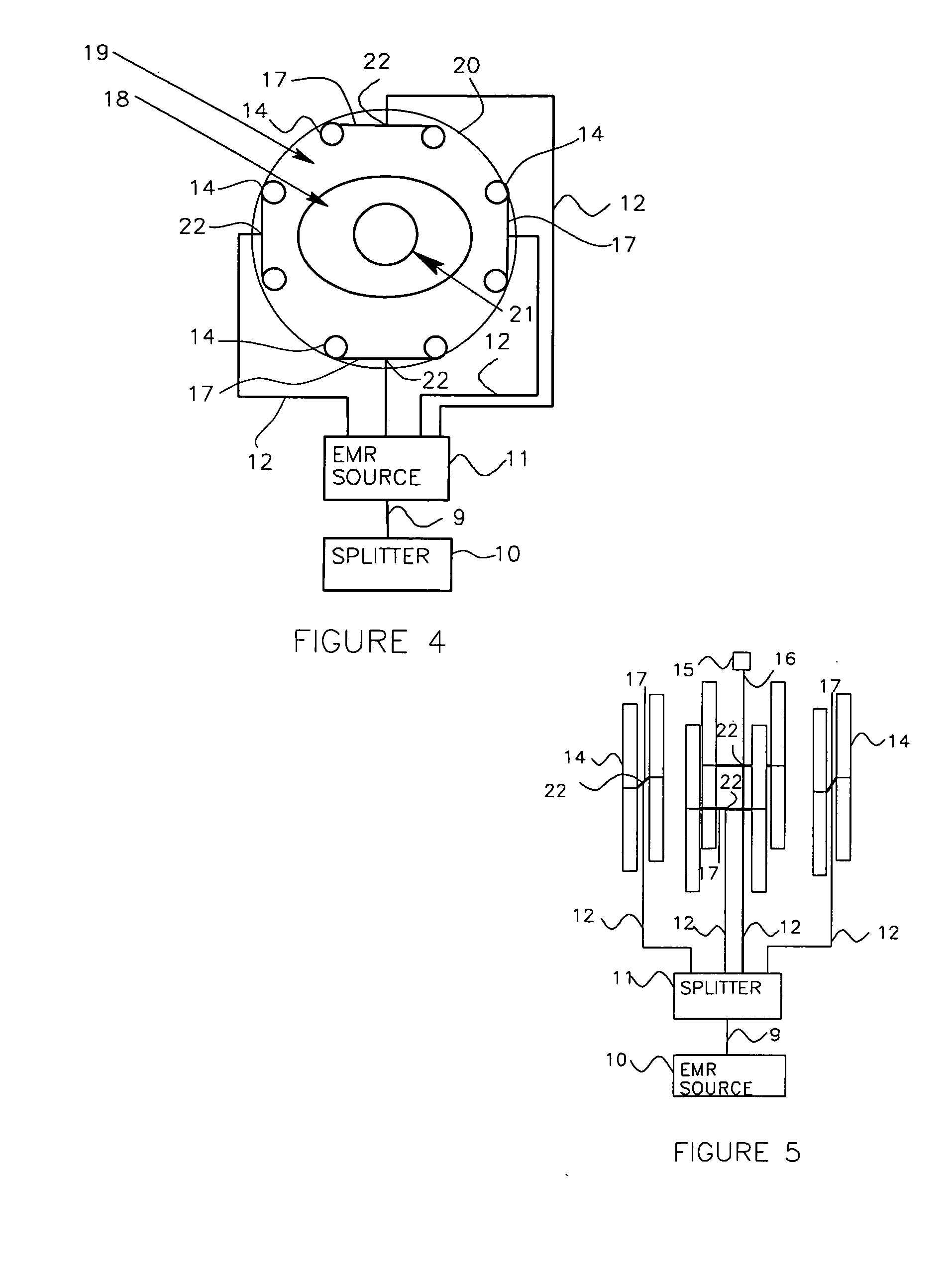
[0018]According to the present invention, a simplified hyperthermia system utilizing an array of electromagnetic radiation applicators utilizes variable reflective termination devices coupled to the applicators to control the phase of the EMR power applied to the individual applicators to steer and control the position of the system heating region in the target. The EMR power can be supplied to the applicators by a single EMR power source and the phase of the EMR radiation directed toward the target by each of the individual applicators is controlled by the variable reflective termination devices. The state of a variable reflective termination device, e.g., whether the termination presents an open circuit or a
short circuit, can be easily varied by a user of the system to control the phase of reflected EMR power at the connection to the applicator, which controls the phase of the radiation from the particular applicator. By controlling the phase of the radiation from each applicator in this manner, the position of the heated region in the target can be steered and controlled without the need for a separate power channel in the EMR power source for each applicator. A single EMR
energy source with a passive power splitter can be used to supply EMR energy of approximately equal power and phase to all applicators through the power splitter and the phase of energy radiated by each individual applicator is easily controlled by the variable reflective termination device.
[0020]The state of a variable reflective termination device, e.g., whether the termination presents an open circuit or a
short circuit, can be varied by a user of the system to control the phase of reflected EMR power at the connection to the applicator, which controls the phase of the radiation from the particular applicator. By controlling the phase of the radiation from each applicator in this manner, the position of the heated region in the target can be steered and controlled without the need for a separate power channel in the EMR power source for each applicator. A single EMR
energy coupling device with a passive power splitter can be used to supply EMR energy of approximately equal power and phase to all applicators through the power splitter. The phase of energy radiated by each individual applicator can be controlled by the variable reflective termination device. Multiple coupling devices can also be used to provide the EMR power to individual or groups of radiating EMR applicators.
[0026]Each applicator can be connected to a variable reflective termination device through a cable of predetermined length that is also connected to the central
energy supply connection point or to a variable
electrical length device such as a variable phase
delay transmission device typically called a passive phase shifter. The length of the cable between the central
energy supply connection point and the variable reflective termination device and the state of the variable reflective termination device determine the apparent state of the central
energy supply connection point to incoming EMR power and determines the phase of the EMR energy radiated from the antennas of the applicator. This arrangement can provide offset heat pattern steering toward the surface of the body while preserving significant deep
heating energy penetration. It provides control to direct the region of heating away from a centered region in the target. For example, in one embodiment the arrangement can be used to target eight offset positions rotated approximately forty-five degrees around the target from one another. The target will usually be a
human patient or
tissue sample to be heated which is positioned in a housing.
[0030]The system of the present invention can be used to provide lower cost and complexity for phased array control of heating patterns in predictable steering positions in a target through the use of variable reflective termination devices to select and control the reflective terminations of at least one of the applicators in an array. In another embodiment, the present invention can be included with a magnetic
resonance imaging system that can provide lower cost and complexity for phased array control of heating patterns in predictable steering positions in a target through the use of variable reflective termination devices to select and control the reflective terminations of at least one of the applicators in an array when combined with an magnetic
resonance imaging system since the expensive high power EMR amplifiers used for the Body Coil can be used for both the imaging and the
tissue heating. The variable reflective termination devices can include open circuit and
short circuit terminations, variable cable lengths, or similar devices. These devices can also be used to create the same effects with parasitic antennas or combinations of primary and parasitic antennas for phase steering of a phased array of antennas. The present invention can provide a simplified annular applicator apparatus for EMR heating for any required purpose, such as medical hyperthermic treatment of cancer or of other medical uses or research.


