System and method for irradiating a target with electromagnetic radiation to produce a heated region

a target and electromagnetic radiation technology, applied in radiation therapy, medical science, radiation therapy, etc., can solve the problems of destroying or inhibiting the patients' natural immunological system, high system complexity and cost in order, and severe adverse side effects at the necessary treatment level, etc., to achieve the effect of simplifying the heat pattern steering

Active Publication Date: 2012-05-01
PYREXAR MEDICAL
View PDF47 Cites 25 Cited by
  • Summary
  • Abstract
  • Description
  • Claims
  • Application Information

AI Technical Summary

Benefits of technology

[0017]It has been observed that the typical operating frequency of a phased array device located in a magnetic resonance imaging system can range between 60 to 200 MHz. The typical magnetic imaging system operated with a magnetic field strength of approximately 1.5 Tesla typically uses radio frequency (RF) power transmitters at a frequency of 63.5 MHz. For a field magnetic strength of approximately 3 Tesla, the transmitter frequency is typically set to 127 MHz. The high power RF transmitter frequency of the MR system is in the same range as that used for the phased array hyperthermia device. To simplify such an integrated system of the phased array hyperthermia with the MR imaging system, it is proposed to provide a novel method to utilize the MR RF power output to also provide the needed power to heat the target using the phased array hyperthermia device that is inserted into the MR aperture.
[0018]According to the present invention, a simplified hyperthermia system utilizing an array of electromagnetic radiation applicators utilizes variable reflective termination devices coupled to the applicators to control the phase of the EMR power applied to the individual applicators to steer and control the position of the system heating region in the target. The EMR power can be supplied to the applicators by a single EMR power source and the phase of the EMR radiation directed toward the target by each of the individual applicators is controlled by the variable reflective termination devices. The state of a variable reflective termination device, e.g., whether the termination presents an open circuit or a short circuit, can be easily varied by a user of the system to control the phase of reflected EMR power at the connection to the applicator, which controls the phase of the radiation from the particular applicator. By controlling the phase of the radiation from each applicator in this manner, the position of the heated region in the target can be steered and controlled without the need for a separate power channel in the EMR power source for each applicator. A single EMR energy source with a passive power splitter can be used to supply EMR energy of approximately equal power and phase to all applicators through the power splitter and the phase of energy radiated by each individual applicator is easily controlled by the variable reflective termination device.
[0020]The state of a variable reflective termination device, e.g., whether the termination presents an open circuit or a short circuit, can be varied by a user of the system to control the phase of reflected EMR power at the connection to the applicator, which controls the phase of the radiation from the particular applicator. By controlling the phase of the radiation from each applicator in this manner, the position of the heated region in the target can be steered and controlled without the need for a separate power channel in the EMR power source for each applicator. A single EMR energy coupling device with a passive power splitter can be used to supply EMR energy of approximately equal power and phase to all applicators through the power splitter. The phase of energy radiated by each individual applicator can be controlled by the variable reflective termination device. Multiple coupling devices can also be used to provide the EMR power to individual or groups of radiating EMR applicators.
[0026]Each applicator can be connected to a variable reflective termination device through a cable of predetermined length that is also connected to the central energy supply connection point or to a variable electrical length device such as a variable phase delay transmission device typically called a passive phase shifter. The length of the cable between the central energy supply connection point and the variable reflective termination device and the state of the variable reflective termination device determine the apparent state of the central energy supply connection point to incoming EMR power and determines the phase of the EMR energy radiated from the antennas of the applicator. This arrangement can provide offset heat pattern steering toward the surface of the body while preserving significant deep heating energy penetration. It provides control to direct the region of heating away from a centered region in the target. For example, in one embodiment the arrangement can be used to target eight offset positions rotated approximately forty-five degrees around the target from one another. The target will usually be a human patient or tissue sample to be heated which is positioned in a housing.
[0030]The system of the present invention can be used to provide lower cost and complexity for phased array control of heating patterns in predictable steering positions in a target through the use of variable reflective termination devices to select and control the reflective terminations of at least one of the applicators in an array. In another embodiment, the present invention can be included with a magnetic resonance imaging system that can provide lower cost and complexity for phased array control of heating patterns in predictable steering positions in a target through the use of variable reflective termination devices to select and control the reflective terminations of at least one of the applicators in an array when combined with an magnetic resonance imaging system since the expensive high power EMR amplifiers used for the Body Coil can be used for both the imaging and the tissue heating. The variable reflective termination devices can include open circuit and short circuit terminations, variable cable lengths, or similar devices. These devices can also be used to create the same effects with parasitic antennas or combinations of primary and parasitic antennas for phase steering of a phased array of antennas. The present invention can provide a simplified annular applicator apparatus for EMR heating for any required purpose, such as medical hyperthermic treatment of cancer or of other medical uses or research.

Problems solved by technology

Such an approach results in high system complexity and cost in order to provide such phased array heat pattern steering.
Although such conventional treatment techniques have been successful in treating cancer in many patients and in prolonging the lives of many other patients, they are frequently ineffective against many types of cancer and often have severe adverse side effects at the necessary treatment levels.
Protracted treatment of cancer patients by X-rays or chemotherapy, as an illustration, tends to eventually destroy or inhibit the patients' natural immunological systems to an extent that many patients eventually succumb to common infectious diseases, such as influenza or pneumonia, which otherwise probably would not be fatal.
Also, many patients having advanced stages of cancer or complications may become too weak to withstand the trauma of surgical or other cancer treatments; hence, the treatments cannot be undertaken or must be discontinued.
Furthermore, many types of malignant cell masses have reportedly been found to have substantially lower heat transfer to lessen the ability to dissipate heat, presumably due to poorer vascularity and reduced blood flow characteristics.
In this regard, researchers have commonly reported that as a consequence of these thermal characteristics of most malignant growths and the thermal sensitivity of normal body cells, hyperthermia temperatures for treatment of human cancer should be carefully limited within a relatively narrow effective and safe temperature range.
However, if large or critical regions of the human body are heated into, or above, the 45 degree C. range for even relatively short times, normal tissue injury may be expected to result.
This results in relatively complicated equipment configurations with multiple channel controls of power and phase.
Such configurations can be difficult for routine clinical professionals to learn and utilize in the clinic.
This allows electronic steering of the heating pattern, but at high cost and complexity.
Such high cost can be cost prohibitive for routine clinical use.
However, the use of complex and expensive multi-channel amplifier systems to provide multiple EMR synchronous phase energy channels that have phase control to steer the heating region in the body has excessive complexity for routine clinical use in some treatment centers.
This temperature change image produced by the MR imaging system can include error effects that are produced by tissue perfusion changes during heating treatments.

Method used


Image

  • System and method for irradiating a target with electromagnetic radiation to produce a heated region
  • System and method for irradiating a target with electromagnetic radiation to produce a heated region
  • System and method for irradiating a target with electromagnetic radiation to produce a heated region

Examples


Embodiment Construction

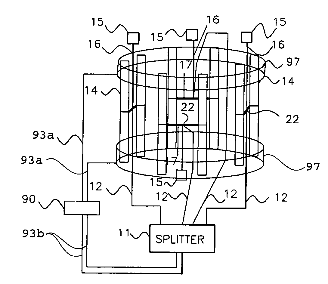
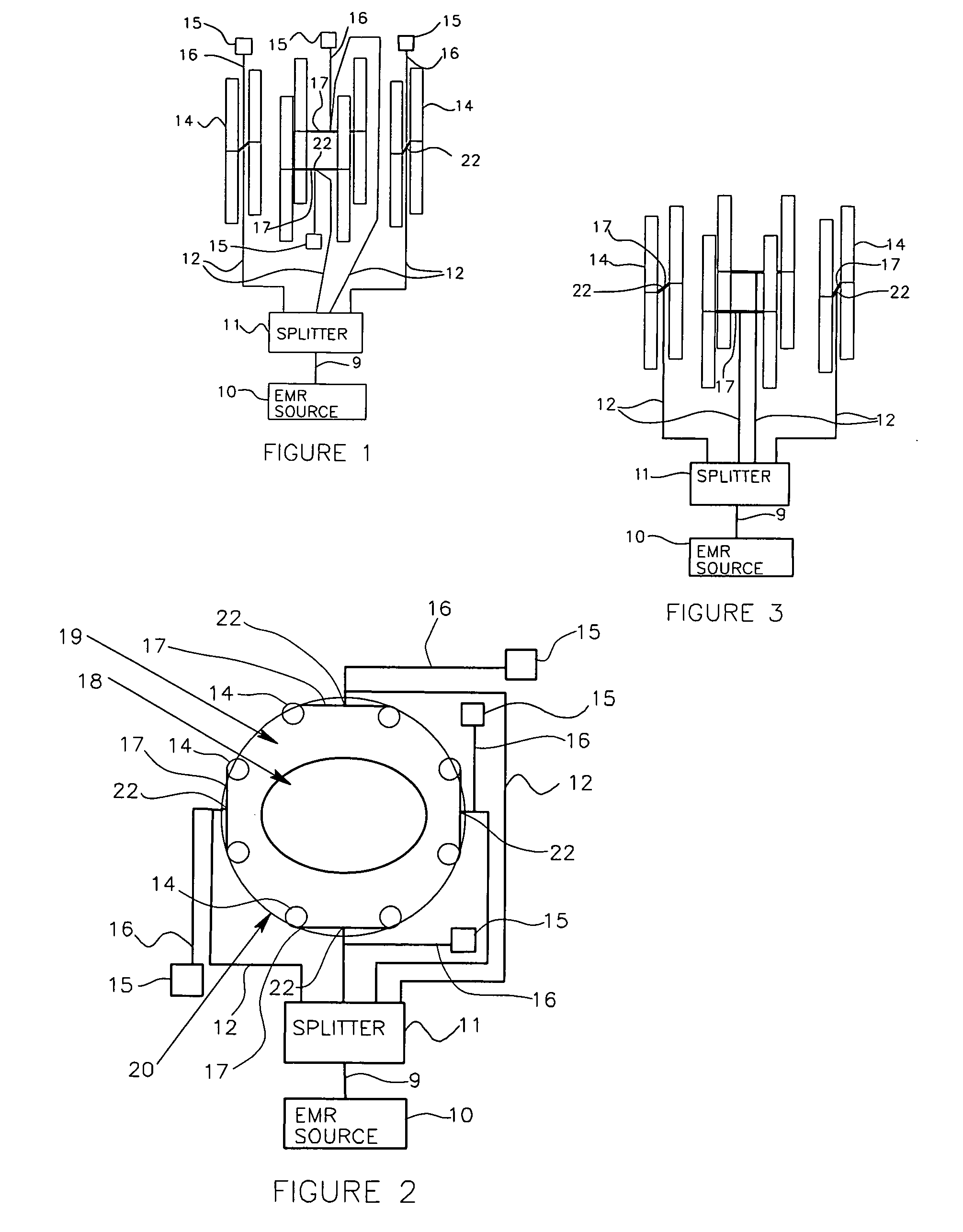
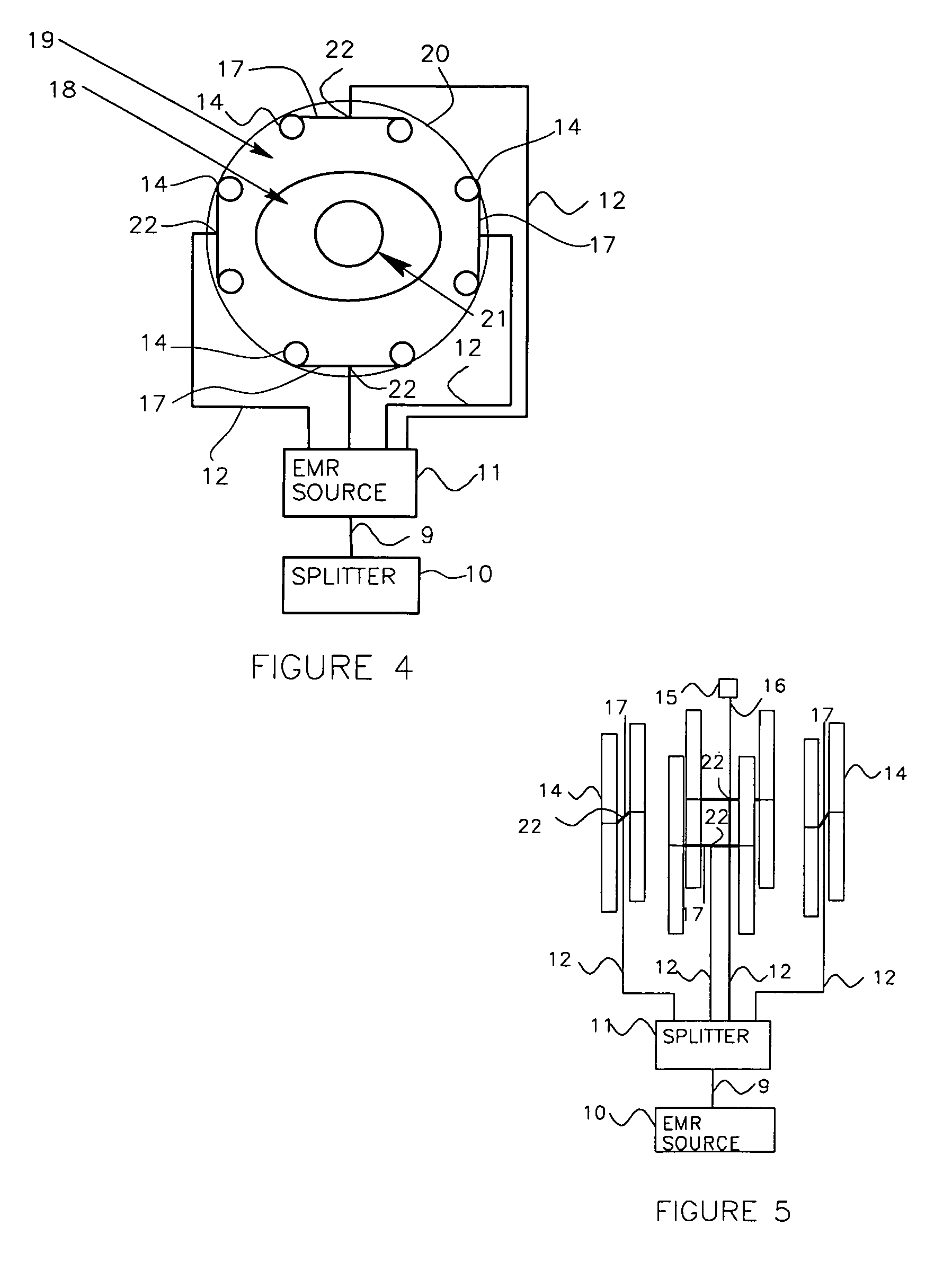
[0057]The apparatus of the invention, as shown in FIG. 1, includes an electromagnetic radiation (EMR) energy source 10 connected to a power splitter 11 that splits the EMR energy from source 10 into a plurality of outputs each connected to one of a plurality of applicators each including one or more antennas 14 connected by cables 17 and having central energy supply connection points 22. The antennas 14 radiate the EMR energy into a body 19, FIG. 2, positioned inside a dielectric shell or housing 20 for heating a target area in the body 19. The radiated energy from the antennas is referred to as a radio frequency heating signal.

[0058]The EMR energy source 10 generally provides EMR energy in a frequency from 40 to 1000 MHz. For heating in human adult torso regions, the preferred frequencies are from 40 to 200 MHz. This is because the penetration losses and the localized heating capability at these frequencies provide for selective targeting and steering in useful regions with adequat...


PUM


Abstract

A system and corresponding method for irradiating a target with electromagnetic radiation to produce a heated region. The system comprises a coupling device operable to couple electromagnetic radiation from a magnetic resonance imaging system. A plurality of energy radiator applicators are connected to the coupling device to receive electromagnetic radiation energy from the coupling device. Each of the radiator applicators is operable to emit a radio frequency heating signal using the electromagnetic radiation energy from the coupling device. A bolus filled with a dielectric fluid is positioned within the inner area of the MRI system. The bolus is operable to receive the radio frequency heating signals from the plurality of energy radiator applicators and direct the radio frequency heating signals into a section of the body to produce a heated region within the body.

Description

CROSS-REFERENCE TO RELATED APPLICATIONS AND CLAIM OF PRIORITY[0001]This is a continuation-in-part of U.S. patent application Ser. No. 11 / 286,104 filed on Nov. 22, 2005, now U.S. Pat. No. 7,565,207, which is herein incorporated by reference.BACKGROUND OF THE INVENTION[0002]1. Field[0003]The present invention relates generally to systems and apparatus for irradiating targets with electromagnetic radiation, and more specifically to systems having annular-type or various sectored applicators and associated control systems for controlling application of radiation to targets through phased array power steering, wherein the phased array system is integratable with a magnetic resonance imaging system.[0004]2. State of the Art[0005]Current systems for applying electromagnetic radiation (EMR) to targets, such as living bodies and biological tissue, and controlling the position of a region of heating within the target through phased array power steering are provided with a plurality of electro...

Claims


Application Information

Patent Timeline
Patent Type & Authority Patents(United States)
IPC IPC(8): A61B5/05A61N5/00
CPCA61N5/02A61N1/403
Inventor TURNER, PAUL F.HAGMANN, MARK
Owner PYREXAR MEDICAL
Why Eureka
Try Eureka