[0010]While both
external fixation devices and PEMF devices are independently useful conventional tools for healing bone and soft tissue injuries, used together they can work in
synergy to improve the overall healing effect. The present application discloses embodiments that combine the useful aspects of
external fixation devices and PEMF devices. Specifically, disclosed embodiments utilize an external fixation support frame that encompasses the injured region, in conjunction with an integrated PEMF device. The disclosed embodiments typically integrate an
electromagnetic coil within the frame structure of the external fixation device, allowing generation of a PEMF field around the injured region.
[0011]The external fixation device of the disclosed embodiments typically uses radial elements to encompass the injured region. The term “encompass” is meant to include embodiments that entirely or partially surround the injured region. Besides encompassing the injury, providing support and stability to the injured body part, the frame of the external fixation device provides a
closed loop path for the PEMF coil, so that the PEMF effect can be generated. The encompassing external frame is generally removably attached to the patient's bone about the injured region. Typically, a connector attaches the frame to the bone, and could be used to removably
affix the frame of the external fixation device to the bone at one or more locations. The connector may, for example, comprise
bone screws, pins, wires, or any other manufactured elements. Beneficially, the PEMF field of the disclosed embodiments may help to reduce the
risk of infection at the point of attachment, providing synergistic benefits. Attaching such an external fixation device to the bone
proximate to an injured region allows the external fixation device to stabilize, compress, and / or distend the injured region, as needed to assist in healing. And by encompassing the injury, the external fixation device may shield the injury from any potential sources of aggravation.
[0012]By its very nature, the encompassing external fixation frame provides beneficial support while minimizing the introduction of any unwanted stresses to the injured region. By encompassing and encircling (either fully or partially) the injured region, the external fixation frame generally maintains a
common point of origin of rotation with the bone, thus holding the bone in a
natural position. Since the bone is supported on opposing sides, no unwanted stresses would be introduced. This is particularly useful, since most conventional
external fixation devices are linear in nature, attaching only to one side of the bone. Such one-sided support means that whenever the bone is rotated into position, compression stresses are introduced at the bone gap. These compression stresses would arise due to the fact that the fixation device is rigidly joined to the bone, but has a pivot point of rotation different from that of the bone. Thus, when a conventional fixation device rotates a bone, it introduces unwanted compressive stresses upon the bone. Naturally, avoiding any such unwanted compression stresses may accelerate the healing process. Therefore, the use of an encompassing external fixation device aids in the healing of an injured region.
[0013]Furthermore, by encompassing the injured region, the external fixation frame of the disclosed embodiments provides a secure platform for mounting the PEMF coils in proximity to the injured region. This configuration provides for substantial coverage of the injured region with the PEMF electromagnetic fields that will stimulate healing. By encircling the injured region with coils, a PEMF field of more uniform density can be targeted to interact holistically with the injured region. The PEMF field of the disclosed embodiments encompasses the injured region, interacting radially with the injury to provide targeted healing from all directions. This targeted approach may accelerate the healing effect of PEMF treatment. PEMF therapy would typically be located near any fracture and / or area of
tissue damage. The PEMF field may increase
bone mineral density throughout the
fracture site, while stimulating tissue growth in the entire region surrounding the fracture. By working together, the encompassing external fixation frame and integrated PEMF coils may decrease the time necessary for healing.
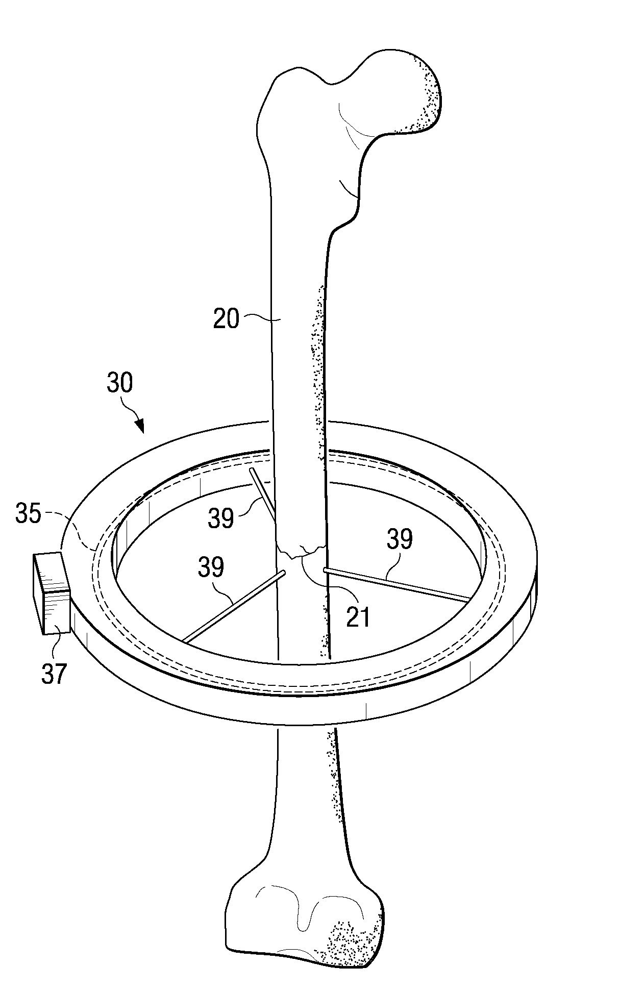
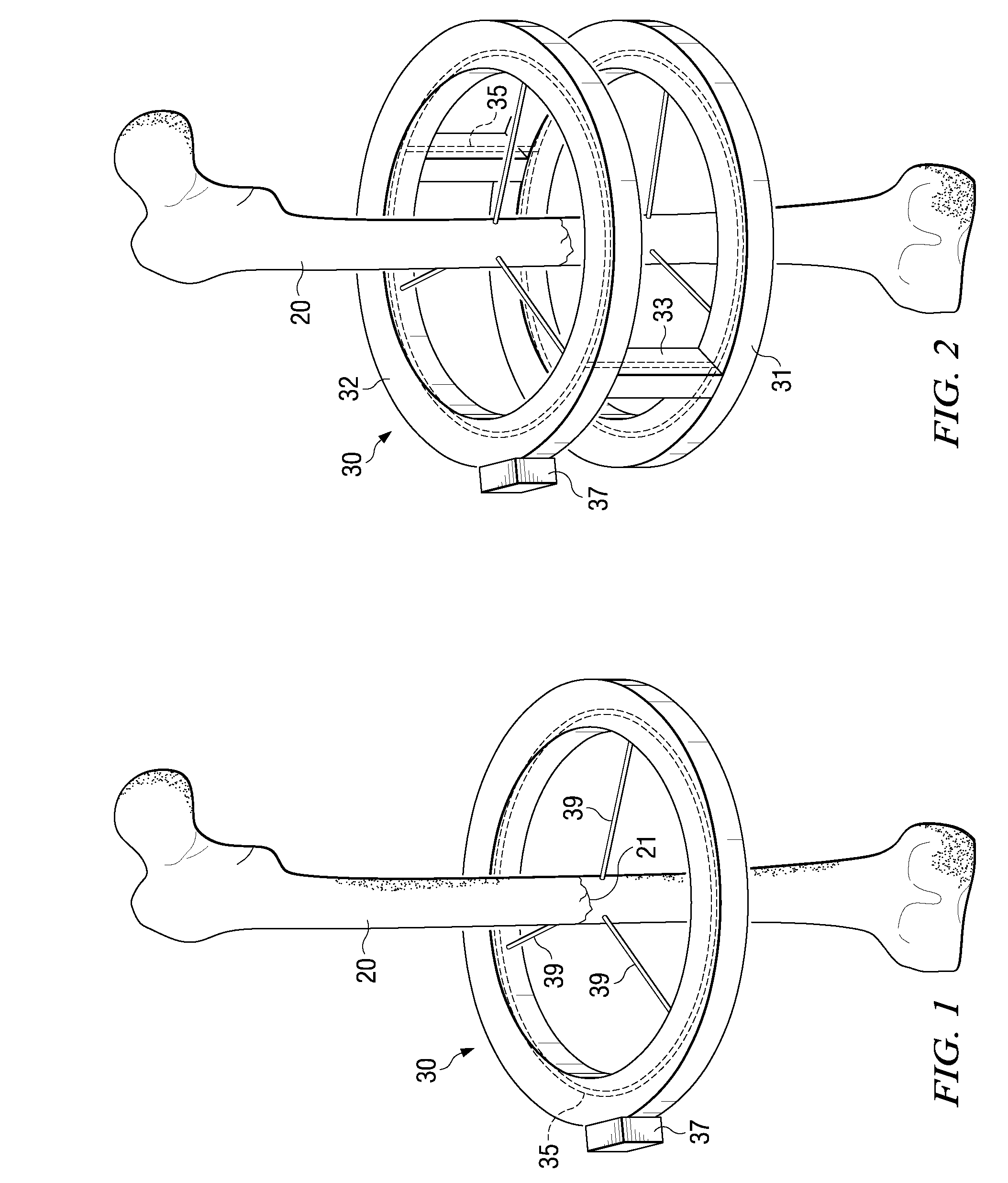
[0014]Depending upon the specific injury being treated, the geometry of the external fixation frame and the PEMF coil may be configured to maximize their effectiveness in treating the injury. By way of example, a small fracture of a
long bone, such as the
tibia, might be treated using an embodiment with a single ring serving as the external fixation frame, encircling the
tibia in proximity to the injured region. In such an embodiment, a coil would typically be integrated within the frame, forming a loop that would project a PEMF field all around the injured region
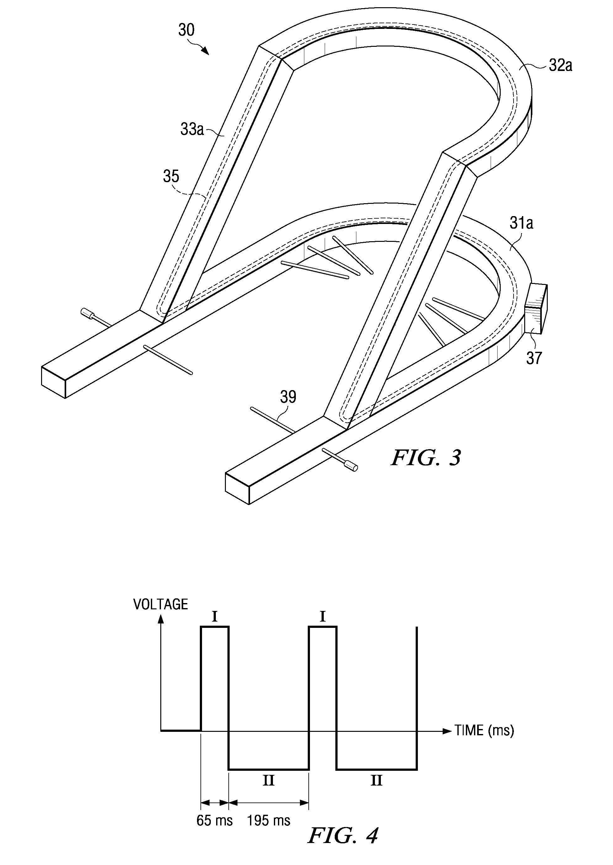
[0017]In one such embodiment, the arch shape of the top element would generally align with the arch of the bottom element's U-shape, and the linking elements would angle up from near the front of the bottom element, angling up and back, and would rigidly attach to the front of the top element. Alternatively, the top and bottom elements of the frame could be oriented in opposite directions, such that the open portions of each element would face each other (although in different, parallel planes), and the linking elements could project upward and forward from the back of the bottom element. Regardless, a continuous loop of PEMF coil would be integrated within the frame to encompass the injured region of the foot, tracing a path along the entire arch of the top element, down one of the linking elements, around the arch of the U-shaped bottom element, back up the opposite linking element to form a
closed loop circuit. A control element may be attached (or possibly integrated) to the fixation frame, such that the
control unit can power the PEMF coil appropriately to generate a PEMF electromagnetic
wave field. Such an embodiment may provide
effective treatment for Charcot foot, or some other such
foot injury, by providing encompassing support (immobilizing the injured region), by shielding the injured foot from further injury, and by providing a PEMF field that can accelerate healing of bone fractures and soft tissue injuries.

