Line Balance Control Method, Line Balance Control Apparatus, and Component Mounting Machine

a technology of line balance control and control apparatus, applied in the direction of total factory control, programme control, instruments, etc., to achieve the effect of improving production efficiency and enhancing production quality

Inactive Publication Date: 2008-09-18
PANASONIC CORP
View PDF9 Cites 19 Cited by
  • Summary
  • Abstract
  • Description
  • Claims
  • Application Information

AI Technical Summary

Benefits of technology

[0017]By this configuration, it is possible to carry out line balance control without using a higher-level device.
[0019]By this configuration, information of each device in a production line is obtained, and on the basis of that information, it is possible to have a desired device executed line balance control.
[0021]By this program, information of each device in a production line is obtained, and on the basis of that information, it is possible to have a desired device executed line balance control.
[0024]By this method, it is possible to carry out line balance control reflecting actual production, and therefore, it is possible to improve production efficiency.
[0035]By this method, it is possible to respond promptly at the time of maintenance of component mounting machines and at the time of malfunction.
[0037]By this method, components with many absorption errors and mounting errors are allocated to other devices, and therefore, it is possible to heighten production quality as well as improvement of production efficiency.

Problems solved by technology

However, the above-described higher-level device is one which requires high processing ability, and there was a problem from the side of cost.

Method used


Image

  • Line Balance Control Method, Line Balance Control Apparatus, and Component Mounting Machine
  • Line Balance Control Method, Line Balance Control Apparatus, and Component Mounting Machine
  • Line Balance Control Method, Line Balance Control Apparatus, and Component Mounting Machine

Examples


first embodiment

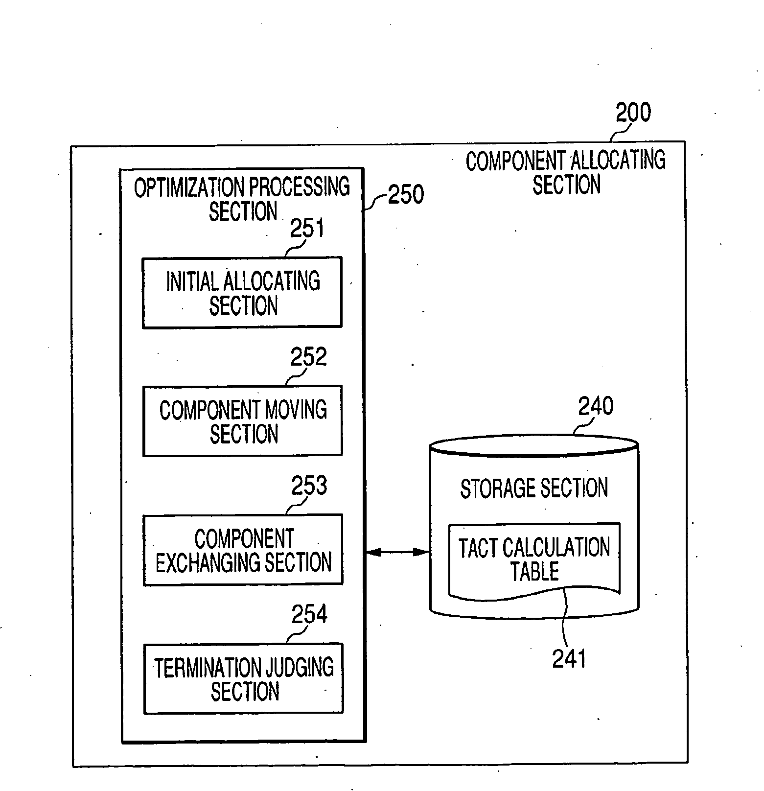
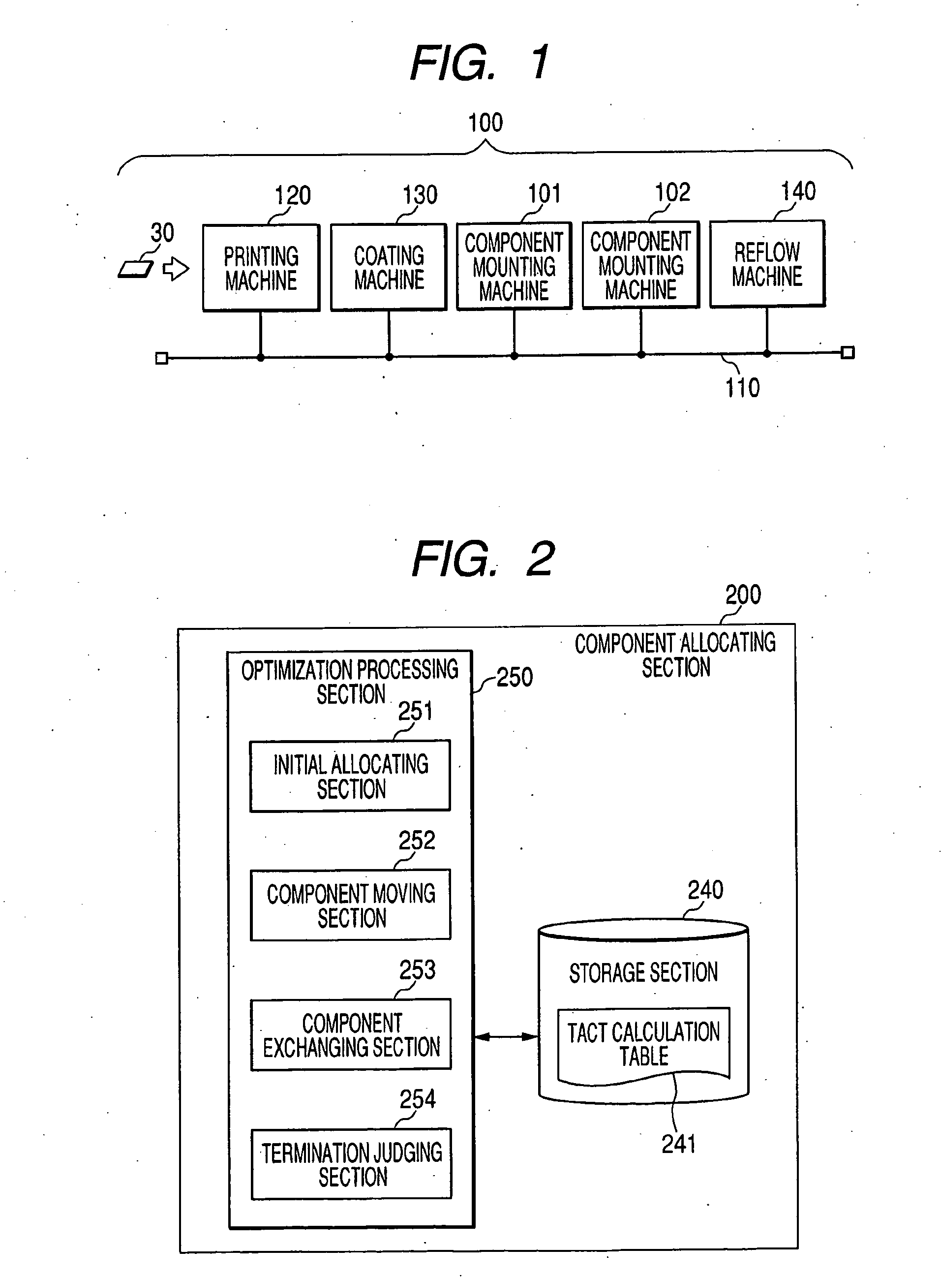
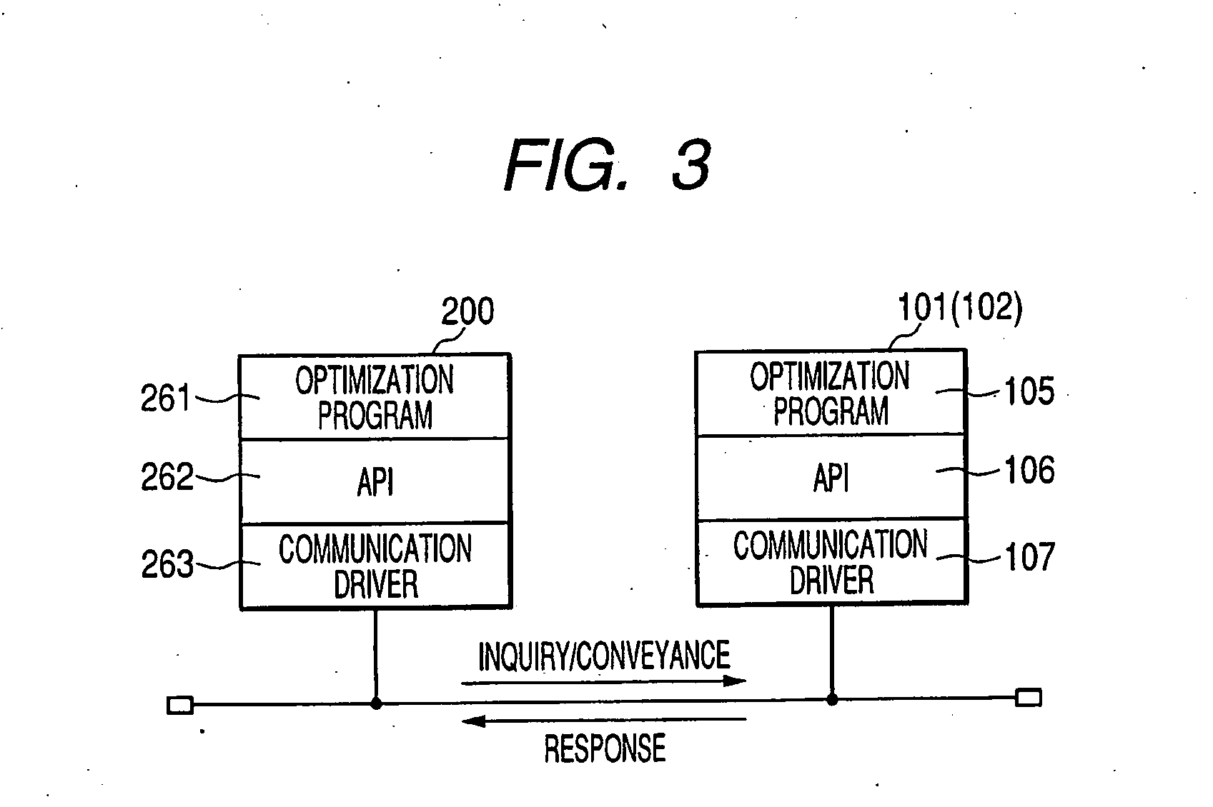
[0072]This embodiment does not dispose a higher-level device for allocating components which becomes mounting objects, in component mounting machines which were disposed in a substrate production line. Alternatively, it is designed in such a manner that the component mounting machine itself and another device which configures the production line carry out the suchlike allocation of components, to carry out equalization (leveling) of tact in each component mounting machine, and to shorten total substrate production time (hereinafter, the suchlike control is referred to as “line balance (control)”). Under the suchlike configuration, there is need to prevent processing load from being concentrated on a device which carries out line balance control. On this account, this embodiment is configured in such a manner that the device, which carries out line balance control, makes an inquiry to component mounting machines, and carries out allocation of components interactively. By the suchlike...

second embodiment

[0146]In the first embodiment, allocation of components is to be carried out by an interactive mode between an apparatus and component mounting machines. However, line balance control according to the first embodiment is a sort of simulation in which it is carried out by use of data which has been already obtained prior to actual production start. Therefore, generation etc. of various phenomena after the actual production start, e.g., errors due to component shortage etc. are not considered. In order to accomplish more accurate line balance, there is need to consider circumstances in an actual production process. The second embodiment of the invention is designed to carry out line balance control reflecting an actual condition of each component mounting machine in a state after start of actual production.

[0147]FIG. 23 is a schematic block diagram which shows a component mounting machine and a line balance control device for explaining the second embodiment of the invention. This emb...

third embodiment

[0187]In the first embodiment, allocation of components is to be carried out by an interactive mode between an apparatus and component mounting machines. Therefore, even in case that a configuration of a production line was changed, it is possible to control line balance flexibly, by holding a talk between component mounting machines again. However, there can be such a case that a component mounting machine, which carries out line balance control, is discarded and removed, along with a change etc. of the production line. In this case, allocation data of which components being allocated to which mounting machine is to disappear, and therefore, it becomes difficult to re-configure a production line including placement of component mounting machines.

[0188]On this account, in this embodiment, on the occasion that a component mounting machine, which carries out line balance control, is discarded and removed, another component mounting machine, which carries out next line balance control,...


PUM


Abstract

To provide a line balance control method, a line balance control apparatus, and a component mounting machine, which do not require a higher-level device. A production line 100 is equipped with a printing machine 120, a coating machine 130, a component mounting machine 101, a component mounting machine 102, and a reflow machine 140, and they are connected through a communication line 110, respectively. In addition, a line balance control device, which is equipped with possibility inquiring means which makes an inquiry of whether or not it is possible to mount components to be allocated, among the components to be mounted, to the component mounting machines 101, 102, possibility obtaining means which obtains a response to the inquiry in the possibility inquiring means, and allocating means which allocates components to be mounted, to each component mounting machine 101, 102, in such a manner that mounting time at each component mounting machine is equalized, on the basis of the response obtained in the possibility obtaining means, is disposed in a device which configure the production line 100.

Description

TECHNICAL FIELD[0001]This invention relates to a line balance control method and a line balance control apparatus, intended for a production line including a plurality of component mounting machine, and a component mounting machine which is included in this production line.BACKGROUND TECHNOLOGY[0002]In the past, in a component mounting line for mounting components such as electronic components onto a substrate such as a printed wiring board, it is important to carry out equalization (leveling) of tact in each component mounting machine that configure the component mounting line, in order to realize shorter tact (mounting time).[0003]On the occasion of carrying out the suchlike equalization of tact, there is such a technology that a higher-level device, which is located in a higher-level of each component mounting machine of the component mounting line, is disposed separately, and this higher-level device becomes an optimization device of a component mounting process, and mounting ob...

Claims


Application Information

Patent Timeline
Patent Type & Authority Applications(United States)
IPC IPC(8): G06F19/00G05B19/418H05K13/04
CPCG05B19/41805G05B19/41865G05B2219/32056G05B2219/45026G05B2219/32297G05B2219/32322G05B2219/33339G05B2219/32258Y02P90/02
Inventor MAENISHI, YASUHIROYOSHIDA, IKUO
Owner PANASONIC CORP
Why Eureka
Try Eureka