Method for manufacturing acceleration sensing unit

Inactive Publication Date: 2008-09-25
SEIKO EPSON CORP
View PDF11 Cites 24 Cited by
  • Summary
  • Abstract
  • Description
  • Claims
  • Application Information

AI Technical Summary

Benefits of technology

[0036]In this way, the concave parts are formed along the directions in which the weight-part supporting part, the element supporting part and the supporting part are respectively broken off. Thereby each supporting part can be easily broken off from the concave part accor

Problems solved by technology

However the weight is situated at the end of the beam in the acceleration sensor according to the example, the beam deformation due to the acceleration concentrates around the fixed part and does not sufficiently works throughout the double-ended tuning-fork type quartz crystal resonator.
Consequently the deformat

Method used


Image

  • Method for manufacturing acceleration sensing unit
  • Method for manufacturing acceleration sensing unit
  • Method for manufacturing acceleration sensing unit

Examples


Example

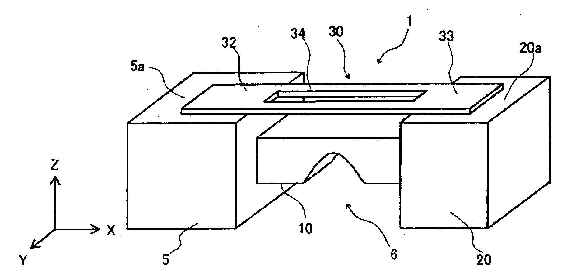
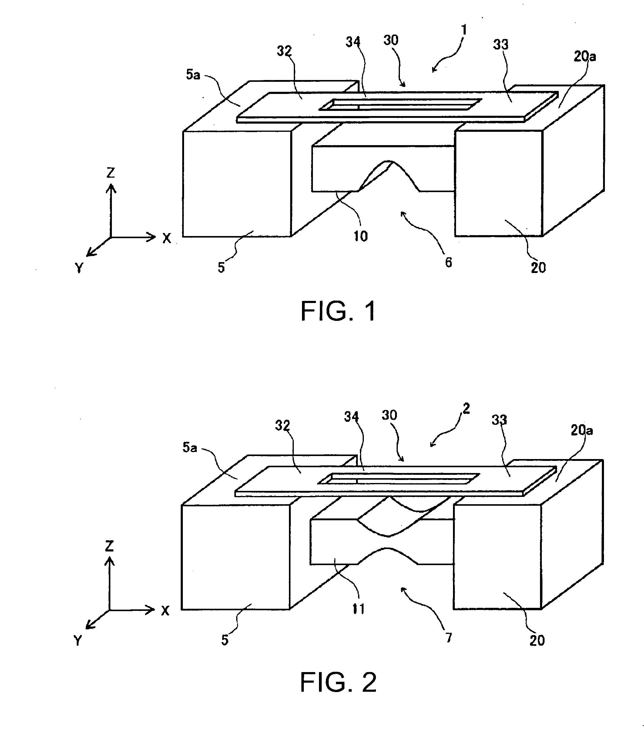
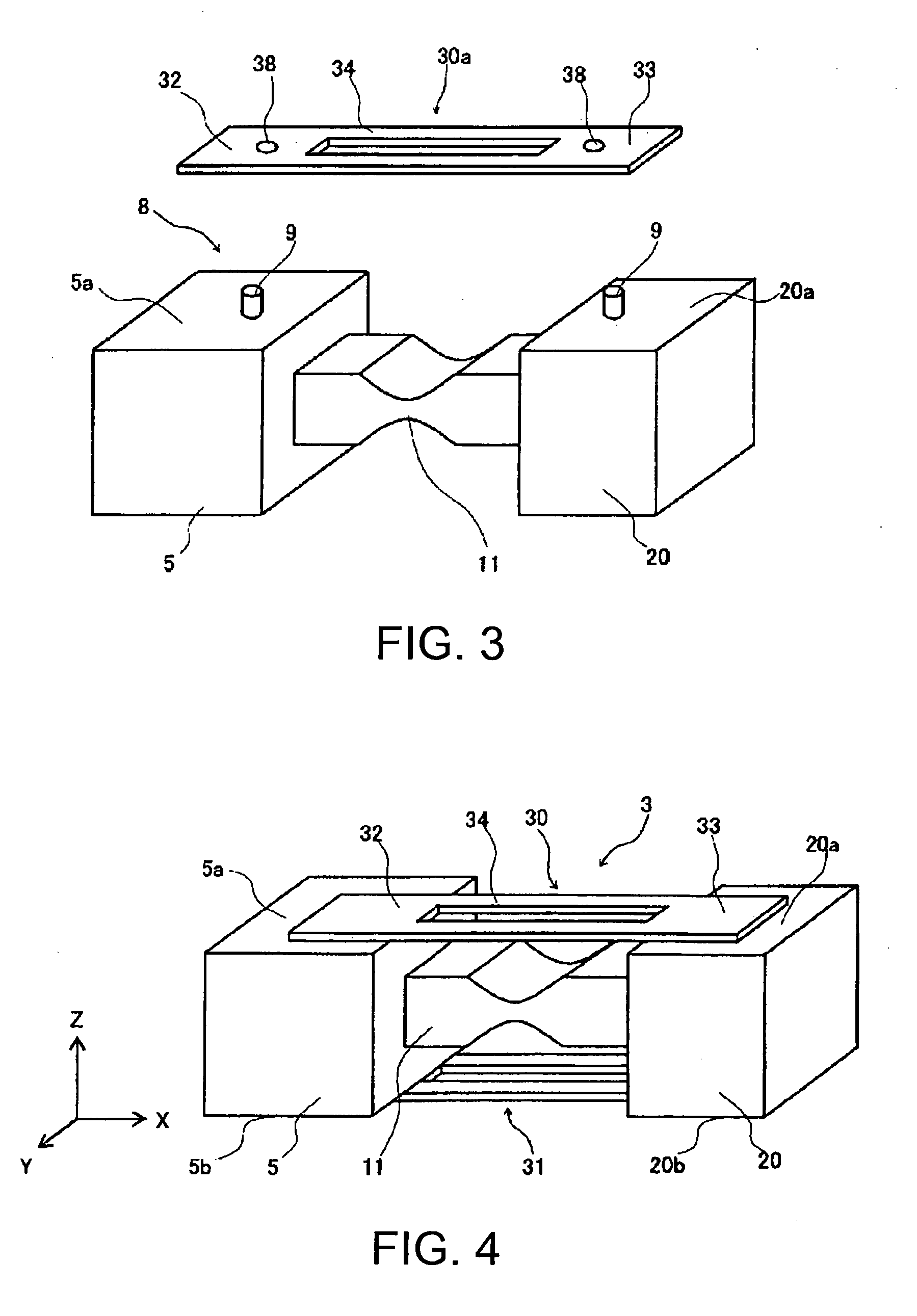
[0052]Embodiments of the invention will be described with reference to the accompanying drawings. FIG. 1 is a perspective view of an acceleration sensing unit 1 according to an embodiment of the invention showing its structure. The acceleration sensing unit 1 includes a fixed part 5 which will not be displaced by acceleration since it is fixedly supported by an unshown fixing part, a movable part 20 which is held movable with respect to the fixed part 5 by a beam 10, and a stress sensing element 30 having a stress sensing part 34 and fixed ends 32, 33 which are formed so as to form a single body with the stress sensing part 34 at its both ends. The beam 10 has a flexibility with which the movable part 20 is displaced in the direction along an acceleration detection axis (Z-axis direction) when an acceleration of the acceleration-detection-axis direction is applied to the movable part 20.

[0053]In the stress sensing element 30, the fixed end 32 is fixed on an upper face of the fixed p...


PUM

PropertyMeasurementUnit
Thicknessaaaaaaaaaa

Abstract

A method for manufacturing an acceleration sensing unit includes: providing an element support substrate in which a plurality of element supporting members is arranged so as to form a plane, each of the element supporting members being coupled to the other element supporting member through a supporting part and having a fixed part and a movable part that is supported by the fixed part through a beam, the beam having a flexibility with which the movable part is displaced along an acceleration detection axis direction when an acceleration is applied to the movable part; providing an stress sensing element substrate in which a plurality of stress sensing elements is arranged so as to form a plane, each of the stress sensing elements being coupled to the other stress sensing element through an element supporting part and having a stress sensing part and fixed ends that are formed so as to have a single body with the stress sensing part at both ends of the stress sensing part; disposing the stress sensing element substrate on the element support substrate such that the fixed ends of each stress sensing element are situated on the fixed part and the movable part; fixing the fixed ends onto the fixed part and the movable part, and dividing the element supporting part and the supporting part.

Description

BACKGROUND OF THE INVENTION[0001]1. Technical Field[0002]The present invention relates to a method for manufacturing an acceleration sensing unit, particularly an acceleration sensing unit in which the same piezoelectric material is used for a stress sensing element and an element supporting member, the element supporting member supports the stress sensing element and deforms when stress is applied, and an etching method is used to form the acceleration sensing unit.[0003]2. Related Art[0004]Acceleration sensors have been widely used for cars, airplanes and rockets, abnormal vibration monitoring systems in plants and the like. JP-A-2-248866 is an example of related art. Referring to FIG. 14, the example discloses a beam structure in an acceleration sensor. In FIG. 14 which is the perspective view of the beam structure, the reference number 90 denotes a double-ended tuning-fork type quartz crystal resonator having two resonating beams 91, the reference number 92 denotes an adhesion p...

Claims


Application Information

Patent Timeline
IPC IPC(8): G01P15/09H01C17/28
CPCG01P15/0802G01P15/097Y10T29/49121Y10T29/49005Y10T29/49103Y10T29/42Y10T29/49126Y10T29/49798Y10T29/49826Y10T29/4913
Inventor SAITO, YOSHIKUNI
Owner SEIKO EPSON CORP
Why Eureka
Try Eureka