Humid air turbine, humid air turbine control system, and humid air turbine control method

a technology of humid air turbines and control systems, which is applied in the direction of machines/engines, mechanical equipment, lighting and heating apparatus, etc., can solve the problems of reducing adversely affecting flame temperature rise, and degrading flame stability, so as to reduce the amount of nox generation and ensure flame stability

Active Publication Date: 2008-09-25
MITSUBISHI POWER LTD
View PDF18 Cites 34 Cited by
  • Summary
  • Abstract
  • Description
  • Claims
  • Application Information

AI Technical Summary

Benefits of technology

[0013]The present invention makes it possible to provide a low NOx combustor and assure flame stability before and after water addition to a humid air turbine.

Problems solved by technology

This decreases the NOx generation amount, but degrades flame stability.
However, if the air flow rate is reduced, the flame temperature rises adversely before the start of water addition.

Method used


Image

  • Humid air turbine, humid air turbine control system, and humid air turbine control method
  • Humid air turbine, humid air turbine control system, and humid air turbine control method
  • Humid air turbine, humid air turbine control system, and humid air turbine control method

Examples


first embodiment

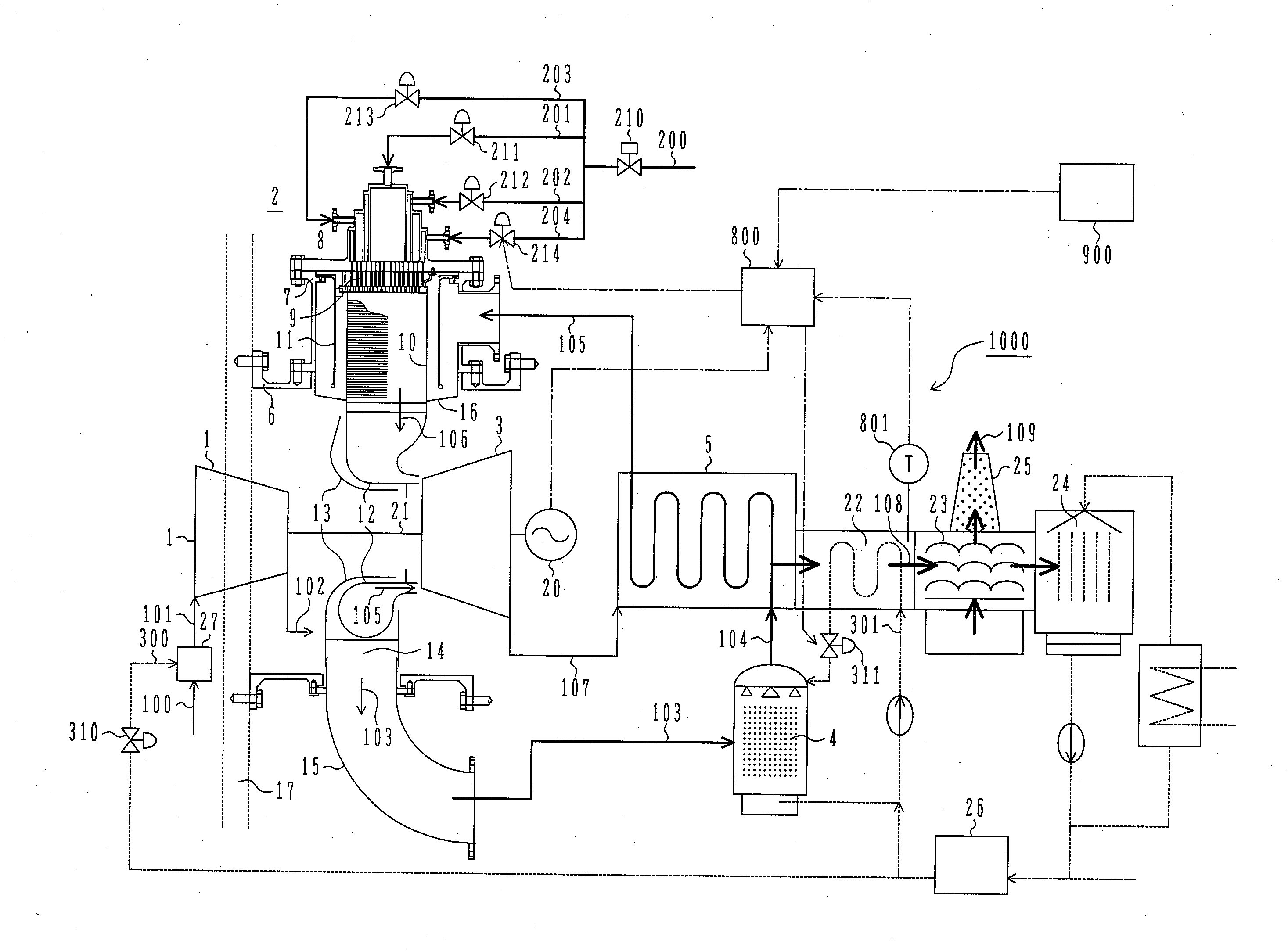
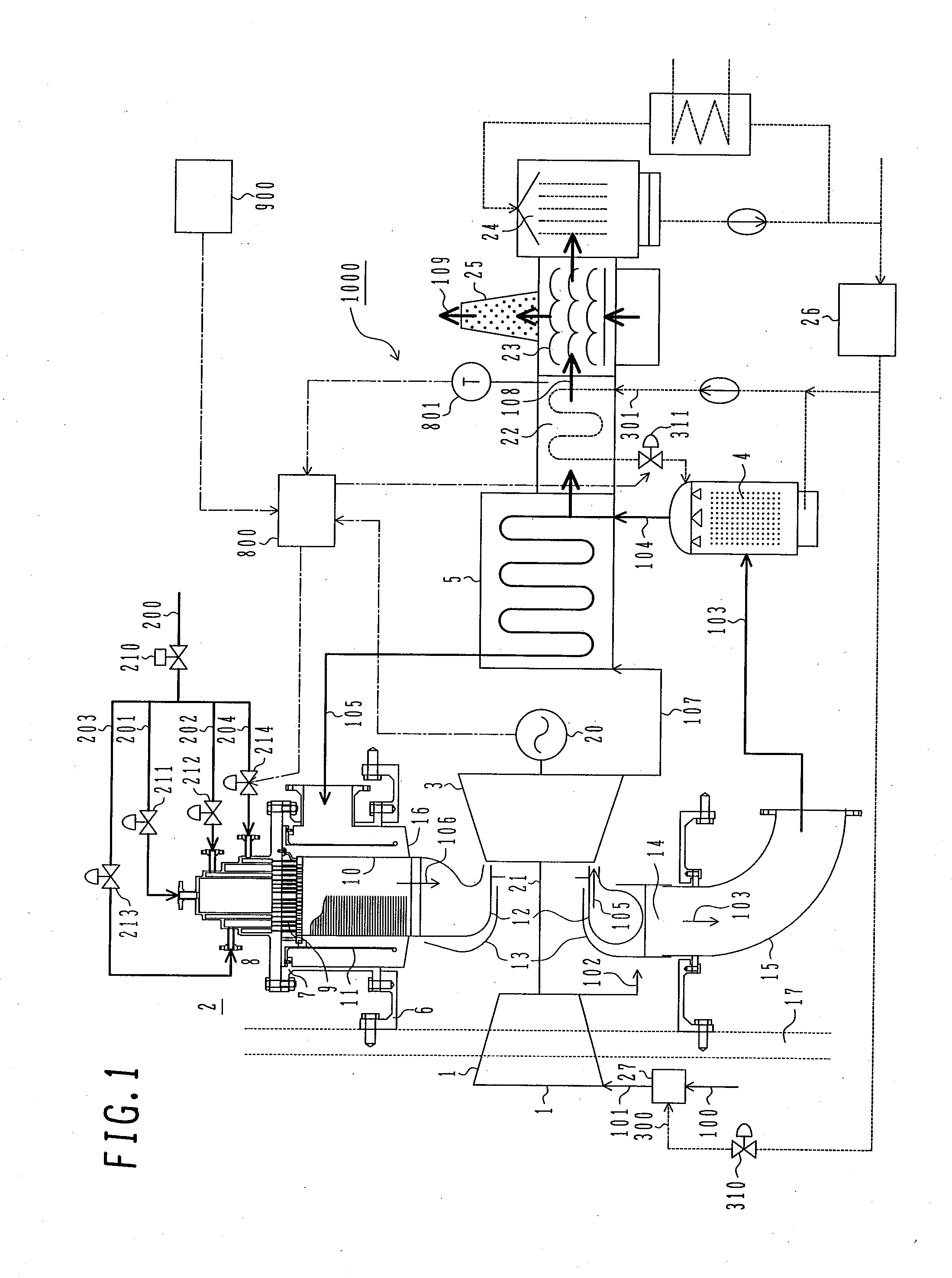
[0070]FIG. 1 is a system flow diagram illustrating the overall configuration of the humid air turbine according to a first embodiment of the present invention.

[0071]The humid air turbine 1000 includes a compressor 1 for compressing air, a combustor 2 for generating combustion gas by burning humid air and fuel, a turbine 3 driven by the combustion gas, a humidificator 4 for generating humid air by adding moisture to compressed air supplied from the compressor, and a recuperator 5 for effecting heat exchange between exhaust from the turbine and the humid air, and acquires electrical power by rotating a power generator 20 through the use of an output from the turbine 3.

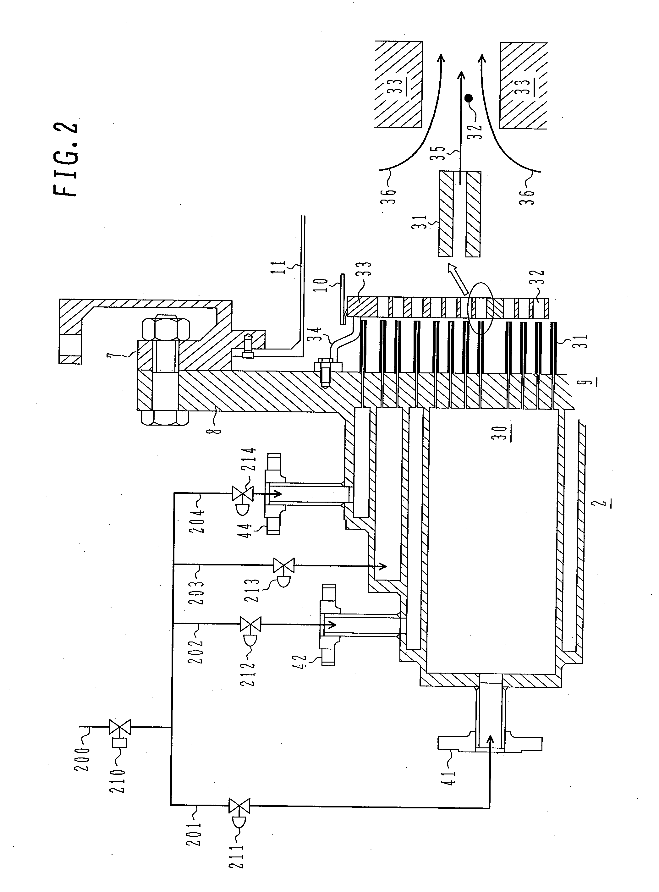
[0072]The combustor 2 is housed inside a main casing 6, a combustor casing 7, and a combustor cover 8. A fuel nozzle 9 is mounted at the center of the upstream end of the combustor 2. A combustor liner 10, which is substantially cylindrical in shape, is positioned downstream of the fuel nozzle 9 to separate unburned air ...

second embodiment

[0099]A second embodiment of the present invention will now be described with reference to FIGS. 7 to 9. FIG. 7 corresponds to FIG. 1 for the first embodiment. FIG. 8 corresponds to FIG. 5. FIG. 9 corresponds to FIG. 4.

[0100]FIG. 7 differs from FIG. 1 in that the humidificator 4 installed in a flow path for the extraction air 103 is replaced by a water atomizer 4a. In this connection, a circulation water system for discharging water from the bottom of the humidificator 4 is also unnecessary.

[0101]In the first embodiment, the water supply amount 301 for the humidificator 4 is larger than the amount of water that is evaporated inside the humidificator 4 and added to the humid air 104. The amount of evaporation in the humidificator 4 is determined by the temperature and pressure of air and water and the evaporation area of the humidificator 4. Therefore, the amount of moisture in the humid air 104 cannot be minutely adjusted.

[0102]On the other hand, the water atomizer 4a used in the pr...


PUM


Abstract

The present invention provides a humid air turbine having a compressor, a humidificator for generating humid air by adding moisture to compressed air supplied from the compressor, a combustor, a turbine, a recuperator for effecting heat exchange between exhaust from the turbine and the humid air, an economizer for effecting heat exchange between exhaust from the recuperator and water, and a system for supplying the water heated by the economizer to the humidificator. The humid air turbine includes a temperature measurement device for measuring the temperature of gas discharged from the economizer, and a control device for adjusting the amount of moisture to be supplied to the humidificator in accordance with a temperature signal from the temperature measurement device. The present invention assures low NOx of combustor and flame stability before and after water addition to the humid air turbine.

Description

BACKGROUND OF THE INVENTION[0001]1. Field of the Invention[0002]The present invention relates to a humid air turbine, humid air turbine control system, and humid air turbine control method.[0003]2. Description of the Related Art[0004]A conventional humid air turbine obtains humid air by adding water to compressed air supplied from a compressor, uses the obtained humid air to recover thermal energy possessed by exhaust discharged from the turbine, and uses the recovered thermal energy to increase its output and efficiency. An invention disclosed in JP-A-2005-307861 provides means for exercising control to stabilize the amount of moisture in air without regard to load variations after the start of water addition in a humid air turbine.[0005]When the rotation speed rises at turbine startup, the flow rate of air taken into the compressor and the vibration characteristic of a rotator generally vary. Therefore, system instability is more likely to result from disturbance than after full s...

Claims


Application Information

Patent Timeline
Patent Type & Authority Applications(United States)
IPC IPC(8): F02C3/30F02C9/00F02C7/22F02C1/00
CPCF01D25/305F01D25/32F02C1/005F23N2041/20F02C3/305F23L2900/00001F02C3/22F23N2241/20
Inventor KOGANEZAWA, TOMOMIKATAGIRI, YUKINORIMIURA, KEISUKE
Owner MITSUBISHI POWER LTD
Why Eureka
Try Eureka