
Electronic actuator for simultaneous liquid flowrate and pressure control of sprayers

Inactive Publication Date: 2008-09-25
RGT UNIV OF CALIFORNIA
View PDF33 Cites 36 Cited by
  • Summary
  • Abstract
  • Description
  • Claims
  • Application Information

AI Technical Summary

Benefits of technology

[0014]The present invention provides a system and method for controlling, independently and selectively, the spray characteristics of each nozzle in the system and permits position and sensor responsive control of the application of liquid materials. Control of individual nozzles allows for more rapid and sophisticated treatment of field zones that may have different application needs. For example, irregular boundaries create overspray difficulties resulting in either sprays on adjacent land or insufficient applications near the boundary line. Similarly, if the operator inadvertently crosses a field boundary or property line, the output of specific nozzles can be managed to avoid the unintentional application of material.
[0015]The selective control of individual nozzles can also associate the application density with the speed of the application vehicle. This will permit a generally uniform application when the vehicle climbs hills, increases or decreases speed or makes turns.
[0016]The system is also open to selective actuation of each nozzle by computer programming and in response to sensor input such as Global Positioning System (GPS) positioning data or infra-red sensors etc. Selective control will allow the application density to be automated and varied in response to specific field topography, vehicle speed, changing weather conditions, diseases and pests or zones for improved precision farming.

Problems solved by technology

For example, irregular boundaries create overspray difficulties resulting in either sprays on adjacent land or insufficient applications near the boundary line.
Each pulse of the valve results in an emission of spray.

Method used


Image

  • Electronic actuator for simultaneous liquid flowrate and pressure control of sprayers
  • Electronic actuator for simultaneous liquid flowrate and pressure control of sprayers
  • Electronic actuator for simultaneous liquid flowrate and pressure control of sprayers

Examples


example 1

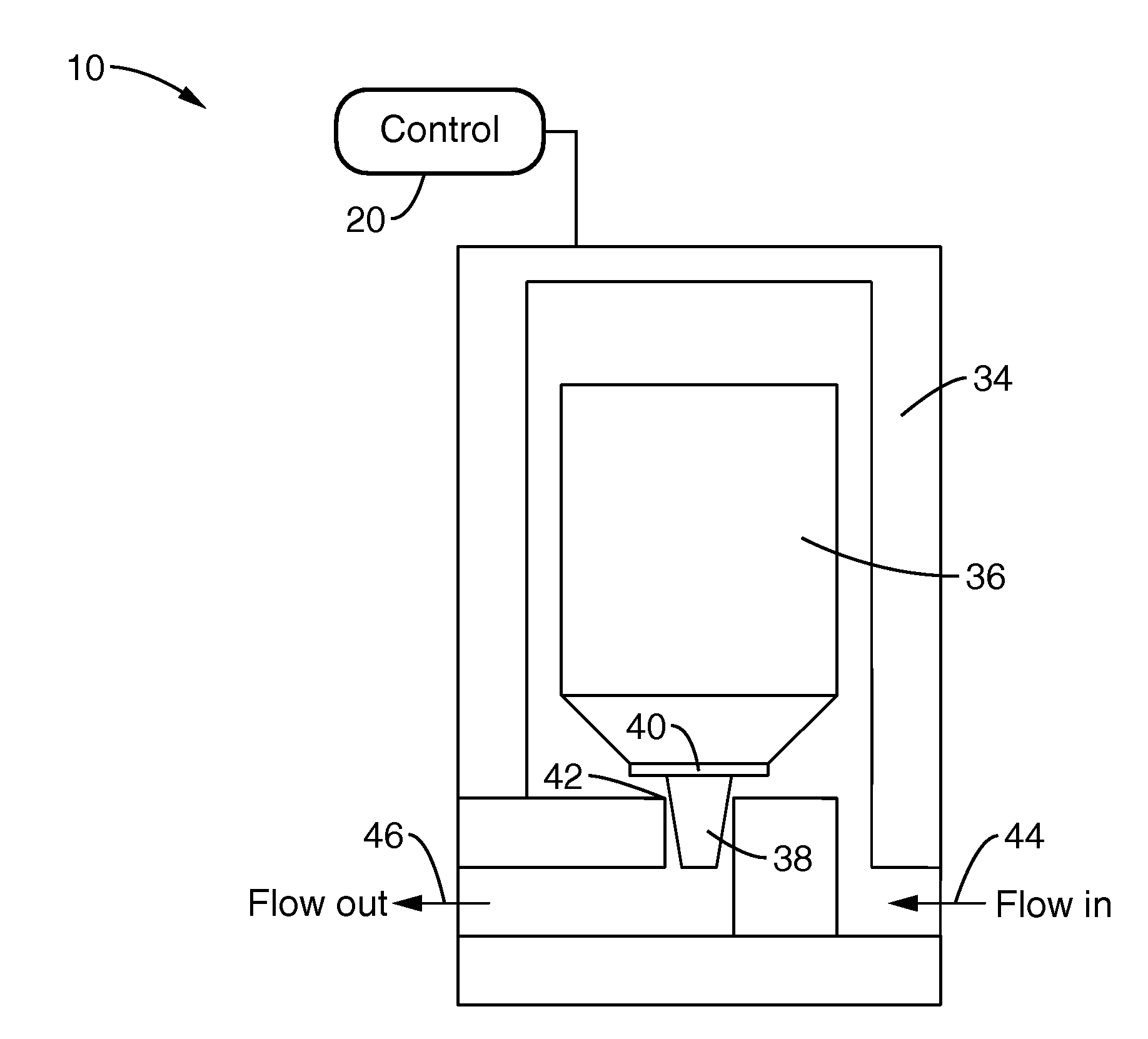
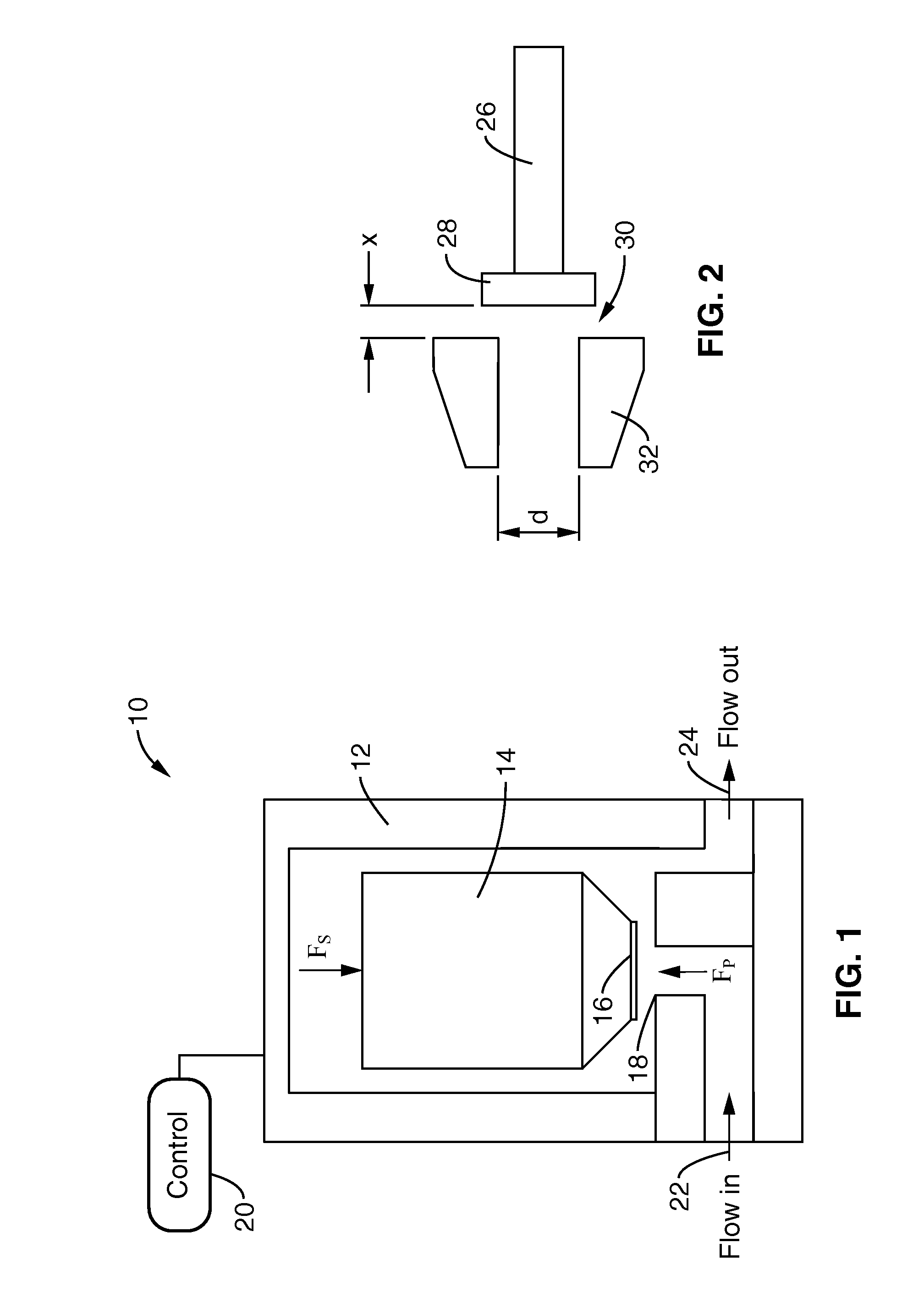
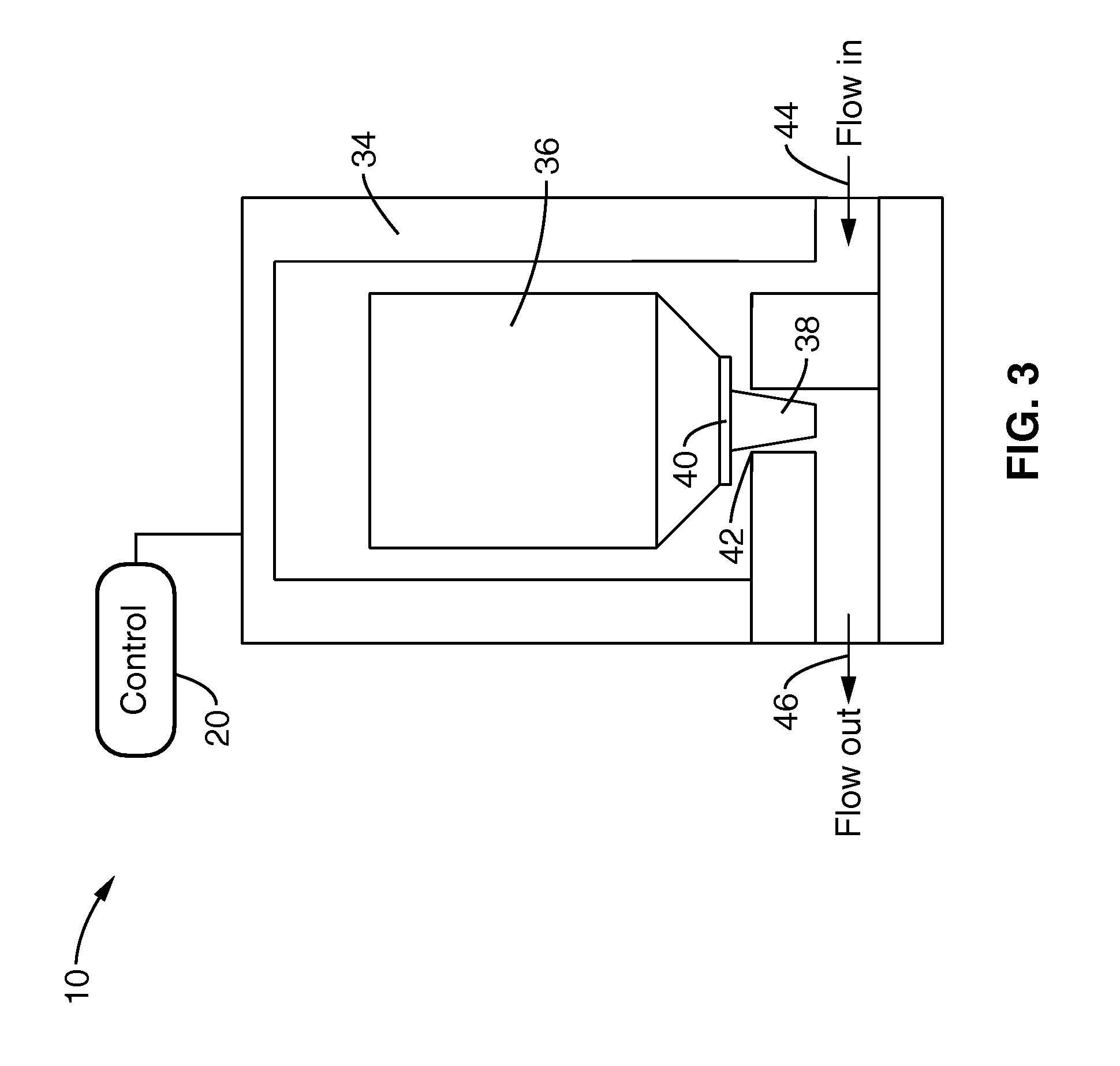
[0056]In order to demonstrate the control of both flowrate and pressure (and corresponding droplet size) through a nozzle, an electric solenoid valve (KIP, Inc. Series 2 valve, 7 W coil) was connected to a liquid (water) reservoir with a constant input pressure of 50 psi. The valve was ported with the pressurized inlet port sealed by the valve poppet as shown schematically in FIG. 1. The outlet was connected with a tee to an Omega PV102-1 OV pressure transducer and to a Spraying Systems 1502 flat fan spray nozzle. An additional spring was added to the valve poppet so that the effective spring constant was doubled.

[0057]The valve was ported “backwards” to avoid the avalanche response for which the valve was designed; the valve was designed to open fully with a threshold voltage, and close fully at a threshold voltage. The added spring helped to seal the valve and the inlet pressure was limited to 50 psi. For higher inlet pressures, a stiffer spring and larger coil are required.

[0058]...

example 2

[0063]The droplet size control was demonstrated using a Kip Series 3 solenoid valve with ¼″ diameter National Pipe Thread (NPT) ports and a 5 / 32″ diameter orifice that was connected to a liquid (water) reservoir with a constant inlet pressure of 95 psi. The valve was ported opposite of the recommended direction with the pressurized inlet port sealed by the valve poppet. The outlet was connected with a tee to an Omega PV102-10V pressure transducer and to a Spraying Systems flat-fan spray nozzle.

[0064]The valve was ported in the reverse direction to avoid the avalanche response for which it was designed. The valve design utilized fluid pressure to open the valve fully with a threshold solenoid current and close fully with a lack of current. Reverse porting avoided the valve's inherent pressure hysteresis characteristics to allow a more controllable outlet response. An additional spring was added behind the valve poppet to increase the effective spring constant and give an additional p...


PUM


Abstract

An electric solenoid valve and electronic circuitry for actuating the valve in such a manner as to control the liquid flow into a device, such as a spray nozzle, is described. By altering the characteristics of the electrical signal driving the valve, the flowrate of liquid through the valve and the pressure drop across the valve during the instantaneous flow can be controlled with a single actuator. The complex waveform of the solenoid drive signal allows decoupled control of droplet size and average flow rate through the nozzle.

Description

CROSS-REFERENCE TO RELATED APPLICATIONS[0001]This application claims priority from U.S. provisional application Ser. No. 60 / 894,562 filed on Mar. 13, 2007, incorporated herein by reference in its entirety.STATEMENT REGARDING FEDERALLY SPONSORED RESEARCH OR DEVELOPMENT[0002]Not ApplicableINCORPORATION-BY-REFERENCE OF MATERIAL SUBMITTED ON A COMPACT DISC[0003]Not ApplicableBACKGROUND OF THE INVENTION[0004]1. Field of the Invention[0005]This invention pertains generally to liquid sprayer systems and more particularly to control of the flowrate of liquid through solenoid actuated nozzle valves and the control of pressure drop across the valves during instantaneous flow in order to provide predictable and controllable droplet sizes, flowrate dispersion density and spray area for each nozzle with a single actuator.[0006]2. Description of Related Art[0007]Modern agriculture is becoming increasingly dependent on the efficient and accurate application of liquid fertilizers and crop protectio...

Claims


Application Information

Patent Timeline
IPC IPC(8): B05B12/00F16K31/06
CPCF16K31/0655B05B9/03
Inventor GILES, DURHAM K.NEEDHAM, DUANE
Owner RGT UNIV OF CALIFORNIA
Learn More