Control of Lattice Spacing Within Crystals

a technology of lattice spacing and crystals, applied in the field of crystals, can solve the problems of limiting the wavelength range over which a device might operate, the inability and the inability to use electric fields to actively control the lattice spacing of colloidal crystals. , to achieve the effect of dynamic positioning of particles, accurate, and reversibl

Inactive Publication Date: 2008-09-25
EASTMAN KODAK CO
View PDF3 Cites 17 Cited by
  • Summary
  • Abstract
  • Description
  • Claims
  • Application Information

AI Technical Summary

Benefits of technology

[0012]The present invention allows accurate, reversible, dynamic positioning of the particles in a suspension. The spacing can be controlled in a rapid, reversible and reproducible manner. The present invention also allows the aspect ratio to be controlled, i.e. the spacing can be different along different axes.

Problems solved by technology

However, none of this prior art suggests the use of an electric field to actively control the lattice spacing of the colloidal crystal assembled in the manner described herein.
A limitation of embedding the photonic crystal within a polymer matrix is that the crystals tend to be polycrystalline in nature.
The range over which the lattice spacing can be tuned within these systems is limited by the flexibility of the polymer matrix, which restricts the wavelength range over which a device might operate.
Typically times in the order of 0.5-1 s are required which makes the photonic crystal in a polymer matrix arrangement unsuitable for a wide range of electro-optical devices, such as optical switches and displays for video-rate applications, that require response times in the order of milliseconds or less.

Method used


Image

  • Control of Lattice Spacing Within Crystals
  • Control of Lattice Spacing Within Crystals
  • Control of Lattice Spacing Within Crystals

Examples


Embodiment Construction

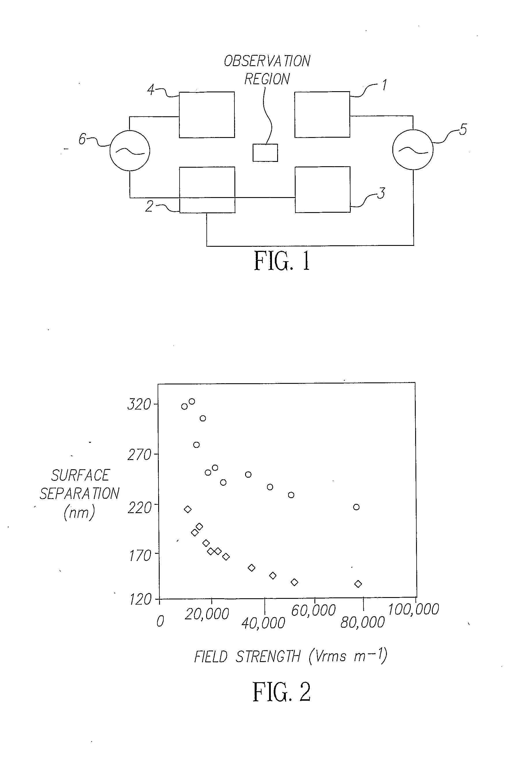
[0018]FIG. 1 illustrates the layout of the electrodes used to demonstrate the method of the invention.

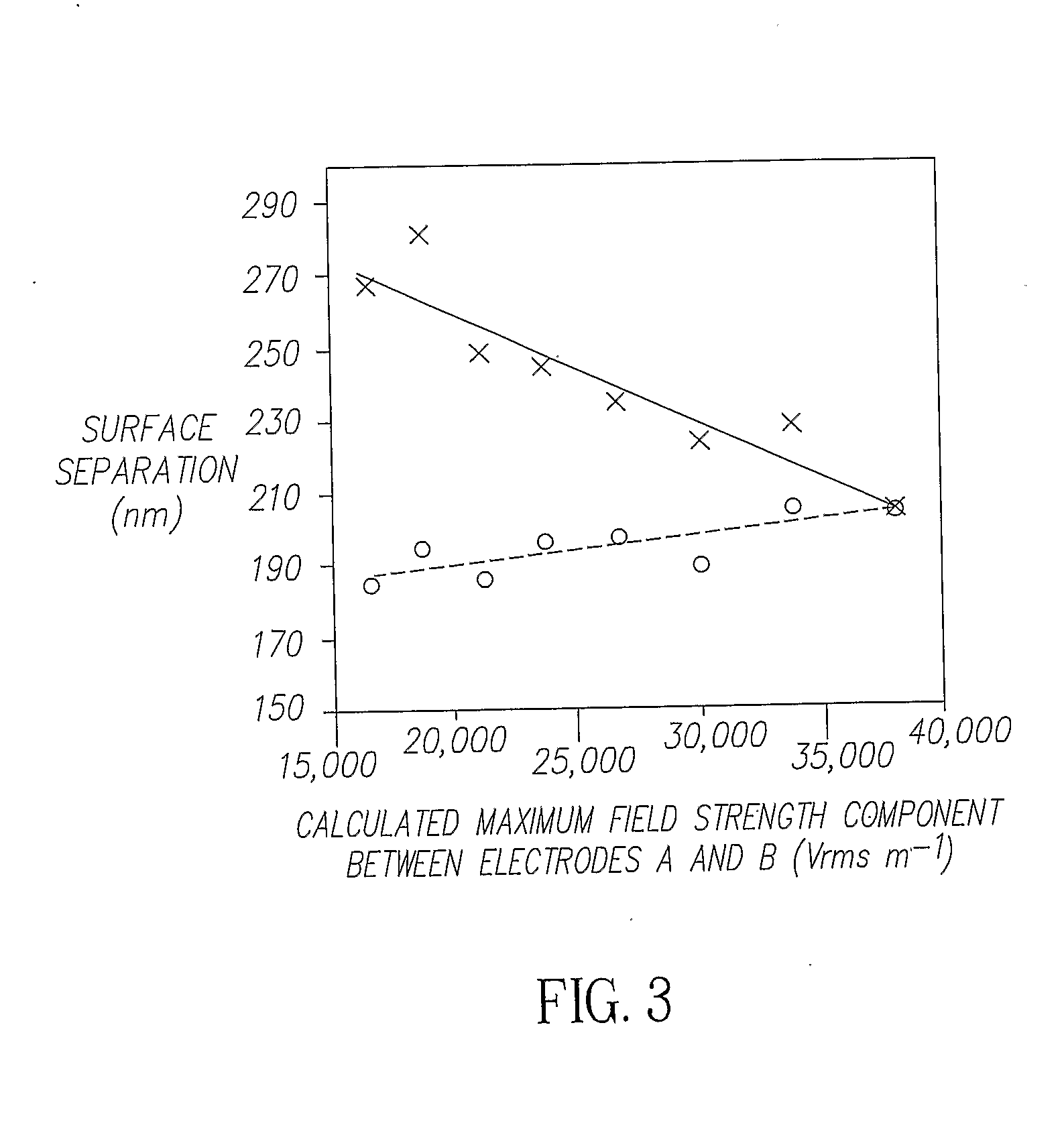
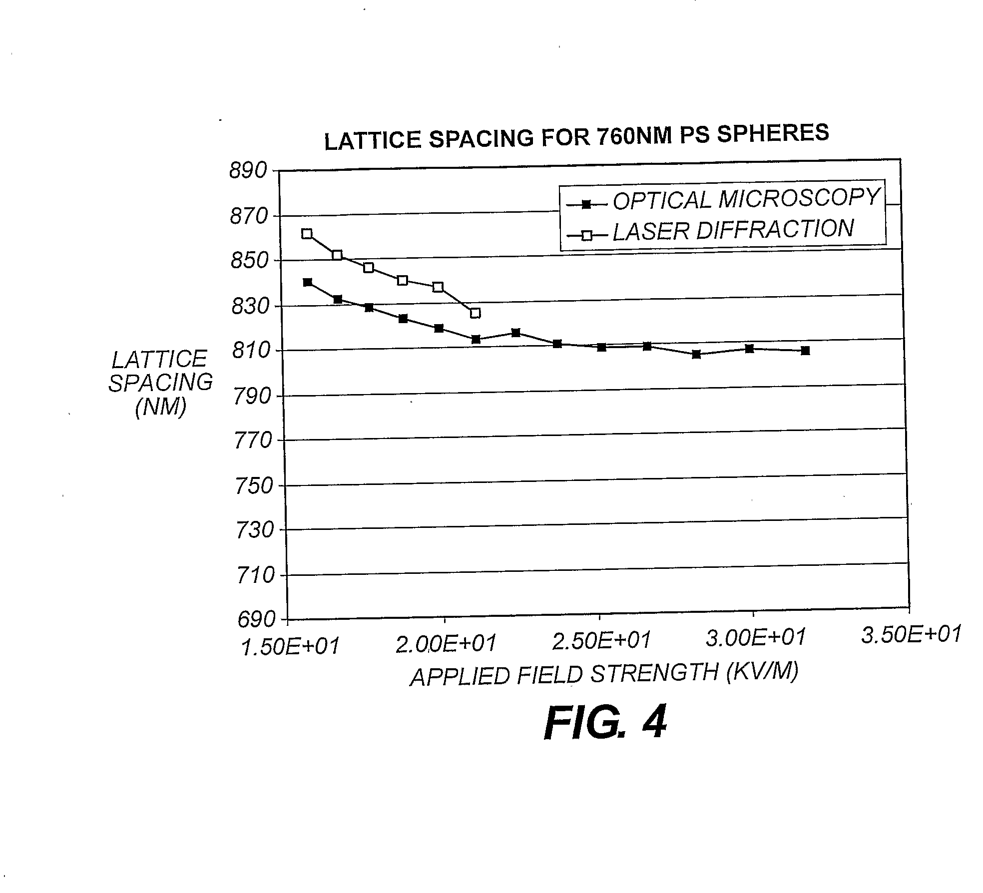
[0019]Four electrodes, 1, 2, 3 and 4, are arranged around an observation region. Electrodes 1 and 2 are connected to a signal amplifier 5. Electrodes 3 and 4 are connected to a signal amplifier 6. The four electrodes are co-planar. In the experiments conducted the distance between electrodes 1, 4 and 2, 3 are 159 μm. The distance between electrodes 1, 3 and 2, 4 are 142 μm. However, the gap can be adjusted as required. Smaller distances mean lower voltages to achieve the desired effect, i.e. a field strength of order 30000 Vm−1.

[0020]The electrodes consist of a 40 nm thick layer of platinum, sputter coated onto a glass microscope slide. Typically a 10 μL aliquot of a dilute suspension of anionic polystyrene latex particles was placed between the electrodes and covered with a microscope coverslip. The edge-to-edge electrical resistance of each electrode was less than 100Ω, resistance...


PUM

PropertyMeasurementUnit
frequencyaaaaaaaaaa
frequencyaaaaaaaaaa
frequencyaaaaaaaaaa

Abstract

A method of creating and controlling the particle spacing of a regular lattice of monodisperse particles or a mixture of monodisperse particles by using an electric field.

Description

FIELD OF THE INVENTION[0001]The invention relates to the field of crystals, in particular to the control of the lattice spacing between the particles in the crystals.BACKGROUND OF THE INVENTION[0002]It is known in the prior art that photonic crystals have a wide variety of applications in optoelectronics, lasers, flat lenses, sensors, wavelength filters and display devices. A common route to fabrication of photonic crystals is to use self-assembly of colloids into colloidal crystals. This self-assembly process can be achieved by a range of different methods such as sedimentation, centrifugation, filtration, shear alignment or evaporative deposition. It is further known that electric fields can be used to assemble close packed arrays of colloids. For example see (Electrophoretic assembly of colloidal crystals with optically tunable micropatterns R. C. Hayward, D. A. Saville & I. A. Aksay, Nature, vol 404, p 56, 2000) and references cited therein. Further examples of colloidal crystal...

Claims


Application Information

Patent Timeline
Patent Type & Authority Applications(United States)
IPC IPC(8): G02B5/20H05F3/00G02B6/12G02B6/122G02F1/00
CPCB82Y20/00G02B6/1225G02F2202/32G02F1/00G02B2006/12166
Inventor BOWER, CHRISTOPHER L.SNOSWELL, DAVIDVINCENT, BRIAN
Owner EASTMAN KODAK CO
Why Eureka
Try Eureka