

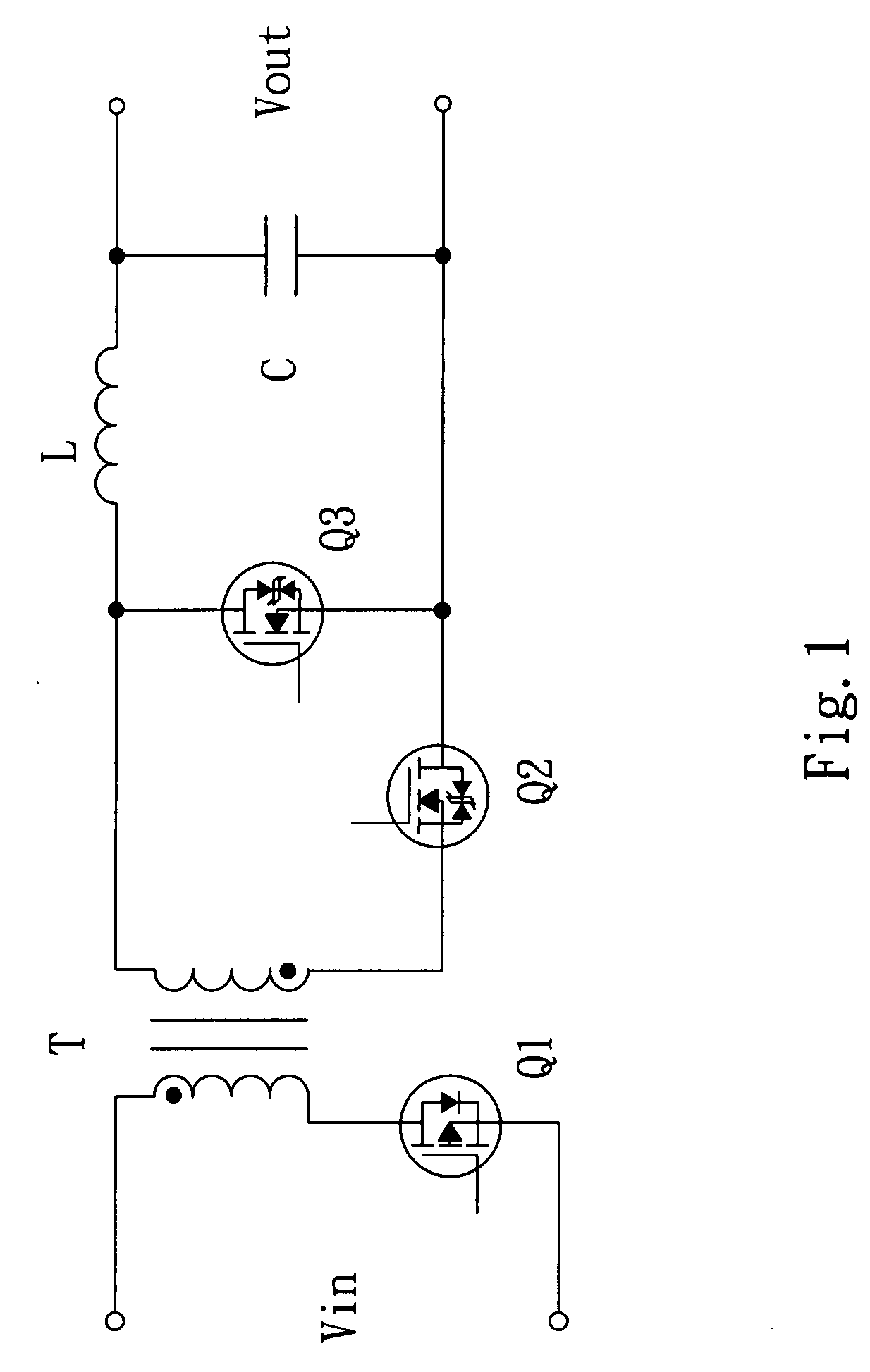
Independent planar transformer
a planar transformer and independent technology, applied in the direction of transformer/inductance details, coils, electrical equipment, etc., can solve the problems of reducing the size of the power transformer and the inductor, requiring a large technique, and requiring a large number of printed circuit boards. , to achieve the effect of reducing material cost effectively, reducing material cost, and flexible and changing
- Summary
- Abstract
- Description
- Claims
- Application Information
AI Technical Summary
Benefits of technology
Problems solved by technology
Method used
Image

Examples
Embodiment Construction
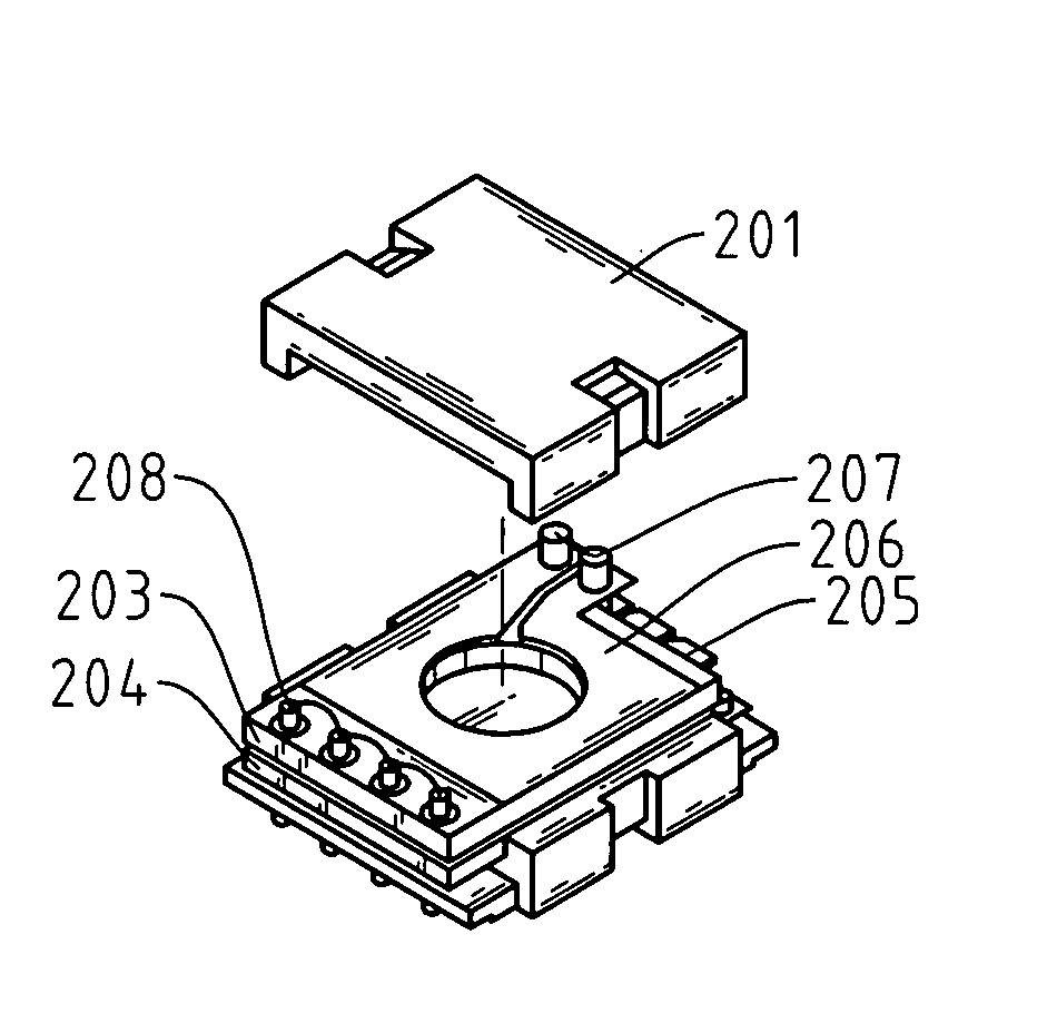
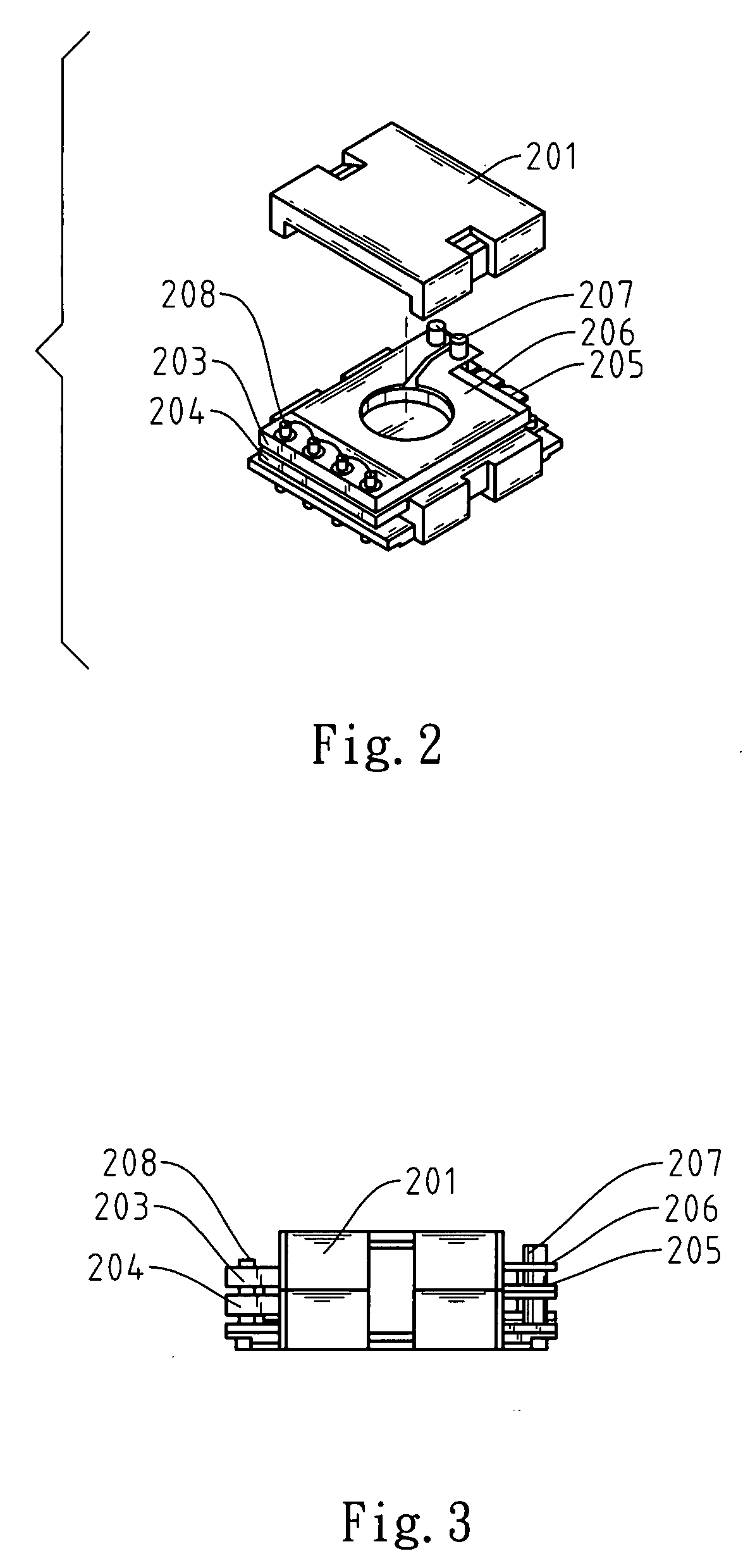
[0026]Referring to FIGS. 2 through 5, there is shown an independent planar transformer, which comprises the devices described below.
[0027]A pair of up-and-down symmetrical ER-type or RM-type soft ferrite magnetic cores (201, 202 or 301, 302).
[0028]At least one printed circuit board (203, 204 or 303) capable of forming different numbers of inductor winding turns to constitute a primary winding of the planar transformer. In other words, the primary winding comprises at least one printed circuit board (203, 204 or 303), and every printed circuit board (203, 204 or 303) has a multi-layer structure having at least two layers to form the inductor winding with at least four turns.
[0029]Two secondary windings comprise at least two planar copper plates (205, 206) or two printed circuit boards (304, 305). Every planar copper plate (205, 206) constitutes one inductor winding turn. Alternatively, the printed circuit boards (304, 305) each have a multi-layer structure having at least two layers ...
PUM
| Property | Measurement | Unit |
|---|---|---|
| supply voltage | aaaaa | aaaaa |
| soft | aaaaa | aaaaa |
| sizes | aaaaa | aaaaa |
Abstract
Description
Claims
Application Information