Liquid crystal device, electronic apparatus and position detecting method

Inactive Publication Date: 2008-09-25
JAPAN DISPLAY WEST
View PDF9 Cites 33 Cited by
  • Summary
  • Abstract
  • Description
  • Claims
  • Application Information

AI Technical Summary

Benefits of technology

[0014]In addition, yet another aspect of the invention provides a method of detecting a position of a pointing body in a liquid crystal device. The liquid crystal device includes a liquid crystal panel and a touch panel. The liquid crystal panel is formed so that a liquid crystal is sealed in a gap between an element substrate and an opposite substrate, which are opposed to each other, and a transmittance ratio of the liquid crystal is controlled on the basis of a voltage applied between a first electrode and a second electrode. The touch panel is arranged on a side of the opposite substrate and provided with a plurality of detection electrodes. The method includes specifying one or plurality of the plurality of detection electrodes in conformity with a predetermined rule, detecting the position of the pointing body on th

Problems solved by technology

In the meantime, parasitic capacitances are formed between the detection electrodes and electrodes or wirings of the liquid crystal device.
Thus, when various signals used for displaying an image vary in the liquid crystal device, there is a problem that noise is induced in the detection electrodes.
Noise

Method used


Image

  • Liquid crystal device, electronic apparatus and position detecting method
  • Liquid crystal device, electronic apparatus and position detecting method
  • Liquid crystal device, electronic apparatus and position detecting method

Examples


Example

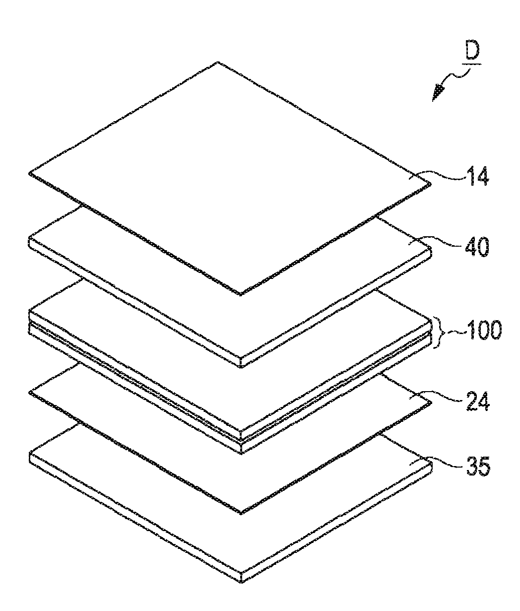
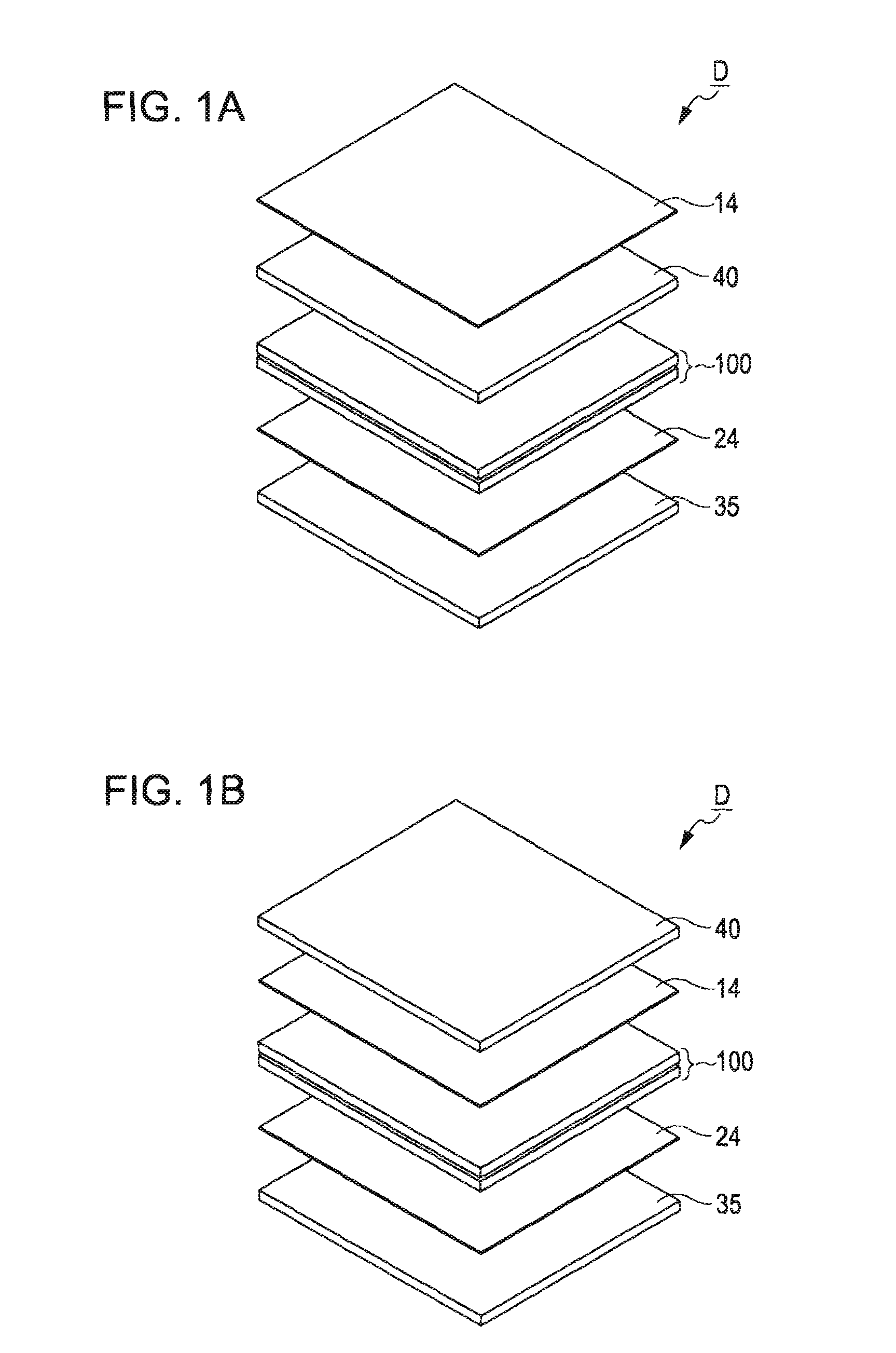
[0031]FIG. 1A and FIG. 1B are exploded perspective views, each of which shows a configuration of a liquid crystal device according to an embodiment of the invention. The liquid crystal device D is an electrostatic-capacitance-type touch panel liquid crystal display device that has a function of displaying an image by means of optical action of a liquid crystal and a function of detecting a position of a pointing body (finger or pen) that is in contact with or is in proximity to the front face of the liquid crystal device D in response to a variation in electrostatic capacitance. As shown in FIG. 1A, the liquid crystal device D includes a liquid crystal panel 100 and a touch panel 40. A polarizer 14 is provided on the upper surface of the touch panel 40 and a polarizer 24 is provided on the lower surface of the liquid crystal panel 100. Moreover, a backlight 35 is provided below the polarizer 24. Then, light emitted from the backlight 35 is optically modulated by the liquid crystal p...


PUM


Abstract

A liquid crystal device includes a liquid crystal panel, a touch panel, a position signal generating device, and a display control device. The liquid crystal panel is formed so that a liquid crystal is sealed in a gap between an element substrate and an opposite substrate, which are opposed to each other, and a transmittance ratio of the liquid crystal is controlled on the basis of a voltage applied between a first electrode and a second electrode. The touch panel is arranged on a side of the opposite substrate and provided with a plurality of detection electrodes. The position signal generating device specifies one or plurality of the plurality of detection electrodes in conformity with a predetermined rule and generates a position signal that indicates a position of a pointing body on the basis of an electric potential of the specified detection electrode or on the basis of electric potentials of the specified detection electrodes. The display control device displays an image of a fixed luminance level on a display area of the liquid crystal panel, which overlaps the detection electrode or detection electrodes specified by the position signal generating device.

Description

BACKGROUND[0001]1. Technical Field[0002]The present invention relates to a technology for identifying a position, at which an object (hereinafter, referred to as pointing body), such as a finger or a pen, contacts a display surface of a liquid crystal device, which displays an image.[0003]2. Related Art[0004]An existing liquid crystal device with a touch panel that uses an electrostatic capacitance method has been proposed. As described in JP-A-5-19233, JP-A-8-44493, JP-A-2000-81610 and JP-T-2003-511799, detection electrodes are formed on a viewing side of the liquid crystal device. The position of the pointing body is identified on the basis of a signal that is obtained by detecting a variation in electrostatic capacitance of the detection electrodes.[0005]In the meantime, parasitic capacitances are formed between the detection electrodes and electrodes or wirings of the liquid crystal device. Thus, when various signals used for displaying an image vary in the liquid crystal device...

Claims


Application Information

Patent Timeline
IPC IPC(8): G06F3/041
CPCG06F3/044G06F3/0412G06F3/0445G06F3/0446
Inventor UTSUNOMIYA, SUMIOKOSHIHARA, TAKESHI
Owner JAPAN DISPLAY WEST
Why Eureka
Try Eureka